In this new guide series, we shall take a look at LvGL and develop driver to display LvGL and touch control.
In this guide, we shall cover the following:
- What is LvGL.
- Required hardware.
- TFT connection.
- Environment setup.
- Essential drivers.
1. What is LvGL:
LvGL is a free and open-source graphics library that allows you to create beautiful and versatile user interfaces for any embedded device, such as microcontrollers, microprocessors, and displays. It has many features, such as widgets, styles, layouts, fonts, animations, and events. It also has a professional UI editor tool, called SquareLine Studio, that lets you design and develop your UIs with drag and drop. LvGL is supported by many vendors and projects, such as Arm, STM32, NXP, Espressif, Arduino, and more. You can learn more about LvGL on its website or GitHub page.
In simple terms, it is Light versatile Graphics Library.
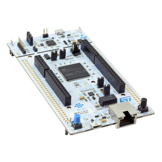
2. Required Hardware:
First we shall use STM32F767ZI Nucleo-144 board as shown in figure below:
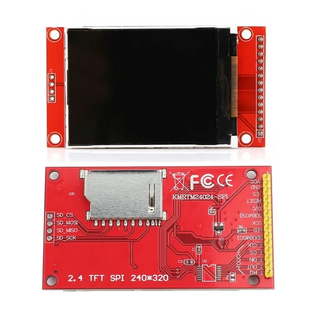
Also, we need 2.4 ILI9341 Touch screen as shown in figure:
3. TFT Connection:
The connection of TFT with STM32 (display only) as following:
| 2.4 TFT SPI | STM32F767ZI-Nucleo144 |
| Vcc | 5V |
| GND | GND |
| CS | PF3 |
| RESET | PF10 |
| D/C | PF5 |
| MOSI | PA7 |
| SCK | PA5 |
| LED | 3V3 |
| MISO | Not needed |
4. Environment setup:
In order to prepare STM32CubeIDE to work with register level programming, we need to setup it up in such way, it allows us to do.
Follow the instruction in this guide here.
Replace STM32F4 with STM32F7
Also, we shall put the header file into folder named driver.
Hence, the project structure looks like this:

Paths:

Symbol should be:
STM32F767xx
Or simply, download the correct project setup from here:
5. Essential Drivers:
First, we need to push the STM32F767 to maximum speed of 216MHz, refer to this guide for how push the core frequency to maximum.
We start by creating new source file with name of sys_init.c:
Within the source file:
Include the following header:
#include "stm32f7xx.h"
Declare the following function:
void SystemInit(void) //set the core frequency to 216MHz
Within the function:
#define PLL_M      4
#define PLL_N      216
#define PLL_P      2

	__IO uint32_t StartUpCounter = 0, HSEStatus = 0;


	RCC->CR |= ((uint32_t)RCC_CR_HSEON);

	do
	{
		HSEStatus = RCC->CR & RCC_CR_HSERDY;
		StartUpCounter++;
	} while((HSEStatus == 0) && (StartUpCounter != 3000));


	if ((RCC->CR & RCC_CR_HSERDY) != RESET)
	{
		HSEStatus = (uint32_t)0x01;
	}
	else
	{
		HSEStatus = (uint32_t)0x00;
	}

	if (HSEStatus == (uint32_t)0x01)
	{

		RCC->APB1ENR |= RCC_APB1ENR_PWREN;
		PWR->CR1 &= (uint32_t)~(PWR_CR1_VOS);


		RCC->CFGR |= RCC_CFGR_HPRE_DIV1;


		RCC->CFGR |= RCC_CFGR_PPRE2_DIV2;


		RCC->CFGR |= RCC_CFGR_PPRE1_DIV4;


		RCC->PLLCFGR = PLL_M | (PLL_N << RCC_PLLCFGR_PLLN_Pos) | (((PLL_P >> 1) -1) << RCC_PLLCFGR_PLLP_Pos) |
				(RCC_PLLCFGR_PLLSRC_HSE);


		RCC->CR |= RCC_CR_PLLON;


		while((RCC->CR & RCC_CR_PLLRDY) == 0)
		{
		}

		/* Configure Flash prefetch, Instruction cache, Data cache and wait state */
		FLASH->ACR = FLASH_ACR_LATENCY_7WS;

		/* Select the main PLL as system clock source */
		RCC->CFGR &= (uint32_t)((uint32_t)~(RCC_CFGR_SW));
		RCC->CFGR |= RCC_CFGR_SW_PLL;

		/* Wait till the main PLL is used as system clock source */
		while ((RCC->CFGR & (uint32_t)RCC_CFGR_SWS ) != RCC_CFGR_SWS_PLL)
		{;}
		}
	else
	{ 	/* If HSE fails to start-up, the application will have wrong clock
			configuration. User can add here some code to deal with this error */
	}
After the core has been set to maximum, we need to enable the floating point hardware and enable cell compensation to improve the speed of the GPIOs as following:
	/*Enable float point hardware*/
	SCB->CPACR |= ((3UL << 10*2)|(3UL << 11*2));

	/*Enable cell compensation*/
	RCC->APB2ENR|=RCC_APB2ENR_SYSCFGEN ;
	SYSCFG->CMPCR|=SYSCFG_CMPCR_CMP_PD;
	while(!((SYSCFG->CMPCR)&(SYSCFG_CMPCR_READY))){;}
Note: This function will be called upon system boot and doesn’t need to be called anywhere else.
Next, LEDs.
Since STM32F767ZI Nucleo-144 features 3-LED, we can create functions to set the state of them.
For more information about the LEDs and how to enable them, please refer to this guide.
Create new source and header file with name of LEDs.c and LEDs.h respectively.
Within the header file:
#ifndef LEDS_H_
#define LEDS_H_

#include "stdint.h"

typedef enum
{
	Green=0,
	Blue=1,
	Red=2
}LEDs;

typedef enum
{
	OFF=0,
	ON=1
}LEDState;

void LEDs_Init(void);

void LED_Write(LEDs led, LEDState state);

#endif /* LEDS_H_ */
Within the source file:
#include "LEDs.h"
#include "stm32f7xx.h"

void LEDs_Init(void)
{
	RCC->AHB1ENR|=RCC_AHB1ENR_GPIOBEN;

	GPIOB->MODER|=GPIO_MODER_MODER0_0|GPIO_MODER_MODER7_0|GPIO_MODER_MODER14_0;
	GPIOB->MODER&=~(GPIO_MODER_MODER0_1|GPIO_MODER_MODER7_1|GPIO_MODER_MODER14_1);
}

void LED_Write(LEDs led, LEDState state)
{
	switch (led)
	{
		case Green:
			if(state==OFF)
			{
				GPIOB->BSRR=GPIO_BSRR_BR0;
			}
			else
			{
				GPIOB->BSRR=GPIO_BSRR_BS0;
			}
			break;

		case Blue:
			if(state==OFF)
			{
				GPIOB->BSRR=GPIO_BSRR_BR7;
			}
			else
			{
				GPIOB->BSRR=GPIO_BSRR_BS7;
			}
			break;

		case Red:
			if(state==OFF)
			{
				GPIOB->BSRR=GPIO_BSRR_BR14;
			}
			else
			{
				GPIOB->BSRR=GPIO_BSRR_BS14;
			}
			break;

		default : break;

	}

}
Also, we need time base for our system, hence, we shall use SysTick.
Create new source and header file with name of time_base.c and time_base.h respectively.
Within the header file:
#ifndef TIME_BASE_H_
#define TIME_BASE_H_

#include "stdint.h"

/*
 * @brief This function will initialize SysTick
 * to generate 1ms interrupt.
 * @param freq source frequency of SysTick.
 * @return nothing.
 * @see Generic ARM CortexM4 user guide.
 * */

void Time_Base_Init(uint32_t freq);

/*
 * @brief This function will return the current millis.
 *
 * @param nothing.
 * @return current time in millis.
 * */
uint64_t Tick_Get();


/*
 * @brief This function will spin lock the CPU to delay for the required
 * amount
 * @param time to be delayed in milliseconds.
 * @return nothing.
 * */
void delay(uint32_t time);


#endif /* TIME_BASE_H_ */
Within the source file:
#include "stm32f7xx.h"
#include "time_base.h"


#define	CTRL_ENABLE					(1U<<0) /*Enable SysTick Timer*/
#define CTRL_CLKSRC					(1U<<2) /*Clock source selection*/
#define CTRL_COUNTFLAG				(1U<<16) /*Count flag bit*/
#define CTRL_TICKINT				(1U<<1) /*Interrupt enable bit*/


volatile uint64_t mil; /*volatile variable to hold the ms counter*/


void Time_Base_Init(uint32_t  freq)
{
	/*Disable global interrupt*/
	__disable_irq();

	/*Set period to be 1ms*/
	SysTick->LOAD=(freq/1000)-1;

	/*Reset the systick value*/
	SysTick->VAL=0;

	/*Enable systick and select internal clk src*/
	SysTick->CTRL = CTRL_ENABLE | CTRL_CLKSRC ;

	/*Enable systick interrupt*/
	SysTick->CTRL  |= CTRL_TICKINT;

	/*Enable global interrupt*/
	__enable_irq();
}

uint64_t Tick_Get(void)
{
	__disable_irq(); /*Disable global interrupt*/

	uint64_t ml=mil; /*Get the current millis values and store in ml*/

	__enable_irq(); /*Enable global interrupt*/

	return ml;		/*Return the stored value*/
}


/*Spin lock the CPU to delay*/
void delay(uint32_t time)
{

	uint64_t start=Tick_Get();
	while((Tick_Get() - start) < (time+1));
}

/*Interrupt handler of SysTick*/
void SysTick_Handler(void)
{
	/*Increment the counter with every interrupt*/
	mil++;

}
Next, we shall use SPI1 to transmit data to the TFT using DMA for LvGL and polling for the initialization sequence.
For more information to transmit data over DMA, please refer to this guide.
For the polling mode from here.
Create new source and header file with name of SPI1.c and SPI1.h respectively.
Within the header file:
#ifndef SPI1_H_
#define SPI1_H_

#include "stdint.h"

void SPI1_Pins_Init(void);

void SPI1_DMA_Init(void);

void SPI1_TX(uint8_t *data,uint32_t size);

void SPI1_TX_DMA(uint8_t *data,uint16_t len);


#endif /* SPI1_H_ */
Source file:
#include "stm32f7xx.h"

#include "SPI1.h"
#include "time_base.h"

#define AF05 0x05

#define CH3 0x03


void SPI1_Pins_Init(void)
{
	//enable clock for GPIOA
	RCC->AHB1ENR|=RCC_AHB1ENR_GPIOAEN;

	//set PA5, PA6 and PA7 to alternate function mode
	GPIOA->MODER|=GPIO_MODER_MODER5_1|GPIO_MODER_MODER6_1|GPIO_MODER_MODER7_1;

	GPIOA->MODER&=~(GPIO_MODER_MODER5_0|GPIO_MODER_MODER6_0|GPIO_MODER_MODER7_0);

	GPIOA->AFR[0]|=(AF05<<GPIO_AFRL_AFRL5_Pos)|(AF05<<GPIO_AFRL_AFRL6_Pos)|(AF05<<GPIO_AFRL_AFRL7_Pos);


}


void SPI1_DMA_Init(void)
{
	//enable clock access to SPI1
	RCC->APB2ENR|=RCC_APB2ENR_SPI1EN;

	//software slave management
	SPI1->CR1|=SPI_CR1_SSM|SPI_CR1_SSI;

	/*Set clock to fPCLK/4*/
	SPI1->CR1 |=(SPI_CR1_BR_0);

	// set SPI as master mode
	SPI1->CR1|=SPI_CR1_MSTR;

	/*Set CPOL to 0 and CPHA to 0*/
	SPI1->CR1 &=~SPI_CR1_CPOL;
	SPI1->CR1 &=~SPI_CR1_CPHA;

	/*Set data size to 8-bit*/
	SPI1->CR2&=~(SPI_CR2_DS_Msk);
	SPI1->CR2|=(0x07<<SPI_CR2_DS_Pos);

	/*Enable TXDMA*/
	SPI1->CR2|=SPI_CR2_TXDMAEN;

	/*Enable SPI global interrupt*/

	NVIC_EnableIRQ(SPI1_IRQn);

	/*Enable SPI peripheral*/
	SPI1->CR1|=SPI_CR1_SPE;

	/*Enable Clock Access to DMA2*/
	RCC->AHB1ENR|=RCC_AHB1ENR_DMA2EN;

	/*Disable the Stream*/
	/*Disable the Stream and make sure it is disabled*/
	DMA2_Stream3->CR&=~DMA_SxCR_EN;

	while((DMA2_Stream3->CR)&DMA_SxCR_EN){;}

	/*Configure the DMA with the following parameters
	 *
	 * CH -> channel 3.
	 * Memory increment mode.
	 * Enable Transfer Complete interrupt
	 * */

	DMA2_Stream3->CR=(CH3<<DMA_SxCR_CHSEL_Pos)|DMA_SxCR_MINC|DMA_SxCR_DIR_0|DMA_SxCR_TCIE;

	/*Enable DMA2_Stream3 interrupt in NVIC*/
	NVIC_EnableIRQ(DMA2_Stream3_IRQn);


}


void SPI1_TX(uint8_t *data,uint32_t size)
{
	uint32_t i=0;
	while(i<size)
	{
		/*Wait until TXE is set*/
		while(!(SPI1->SR & (SPI_SR_TXE)))
		{}

		/*Write the data to the data register*/
		*((volatile uint8_t *)&SPI1->DR) = data[i];
		i++;
	}
	/*Wait until TXE is set*/
	while(!(SPI1->SR & (SPI_SR_TXE))){}

	/*Wait for BUSY flag to reset*/
	while((SPI1->SR & (SPI_SR_BSY))){}

	/*Clear OVR flag*/
	(void)SPI1->DR;
	(void)SPI1->SR;
}


void SPI1_TX_DMA(uint8_t *data,uint16_t len)
{


	DMA2->LIFCR |=DMA_LIFCR_CTCIF3;
	DMA2_Stream3->PAR=(uint32_t)&SPI1->DR;
	DMA2_Stream3->M0AR=(uint32_t)data;
	DMA2_Stream3->NDTR=len;
	DMA2_Stream3->CR|=DMA_SxCR_EN;

}


__WEAK void SPI_TX_Finished(void)
{
	/*Override with user code*/
}


void DMA2_Stream3_IRQHandler(void)
{
	if(DMA2->LISR&(DMA_LISR_TCIF3))
	{
		/*Enable SPI Tx buffer empty interrupt */

		SPI1->CR2|=SPI_CR2_TXEIE;

		/*Clear pending flag*/
		DMA2->LIFCR |=DMA_LIFCR_CTCIF3;
	}
}

void SPI1_IRQHandler(void)
{
	if ((SPI1->SR & SPI_SR_TXE) && ((SPI1->SR & SPI_SR_BSY)==0))
	{
		/*Set finished to 1*/
		SPI_TX_Finished();

		/*Disable SPI Tx Buffer empty interrupt*/
		SPI1->CR2&=~SPI_CR2_TXEIE;


	}
}
Now, we shall deal with the LCD pins.
Create new source and header file with name of LCD_Pins.c and LCD_Pins.h.
Within the header file:
#ifndef LCD_PINS_H_
#define LCD_PINS_H_

#include "stdint.h"

void LCD_Pins_Init(void);

void CS_LOW(void);

void CS_HIGH(void);

void DC_LOW (void);

void DC_HIGH (void);

void LCD_RST(void);


#endif /* LCD_PINS_H_ */
Within the source file:
#include "LCD_Pins.h"

#include "stm32f7xx.h"
#include "time_base.h"
/*Connection
 *
 * PF3 ->CS
 * PF5 ->DC
 * PF10 ->RST
 *
 * */


void LCD_Pins_Init(void)
{
	RCC->AHB1ENR|=RCC_AHB1ENR_GPIOFEN;

	GPIOF->MODER|=GPIO_MODER_MODER3_0|GPIO_MODER_MODER5_0|GPIO_MODER_MODER10_0;
	GPIOF->MODER&=~(GPIO_MODER_MODER3_1|GPIO_MODER_MODER5_1|GPIO_MODER_MODER10_1);

	/*Set CS and RST to high*/
	GPIOF->BSRR=GPIO_BSRR_BS3|GPIO_BSRR_BS10;
}


void CS_LOW(void)
{
	GPIOF->BSRR=GPIO_BSRR_BR3;
}

void CS_HIGH(void)
{
	GPIOF->BSRR=GPIO_BSRR_BS3;
}

void DC_LOW (void)
{
	GPIOF->BSRR=GPIO_BSRR_BR5;
}

void DC_HIGH (void)
{
	GPIOF->BSRR=GPIO_BSRR_BS5;
}

void LCD_RST(void)
{
	GPIOF->BSRR=GPIO_BSRR_BR10;
	delay(100);
	GPIOF->BSRR=GPIO_BSRR_BS10;
	delay(10);

}
Next, we shall deal with TFT.
Create new source and header file with name of ILI_9341.c and ILI_9341.h respectively.
Within the header file:
#ifndef ILI_9341_H_
#define ILI_9341_H_


#include "stdint.h"


//LCD dimensions defines
#define ILI9341_WIDTH       320
#define ILI9341_HEIGHT      240


#define ILI9341_PIXEL_COUNT	ILI9341_WIDTH * ILI9341_HEIGHT


//ILI9341 LCD commands
#define ILI9341_RESET			 		    0x01
#define ILI9341_SLEEP_OUT		  			0x11
#define ILI9341_GAMMA			    		0x26
#define ILI9341_DISPLAY_OFF					0x28
#define ILI9341_DISPLAY_ON					0x29
#define ILI9341_COLUMN_ADDR					0x2A
#define ILI9341_PAGE_ADDR			  		0x2B
#define ILI9341_GRAM				    	0x2C
#define ILI9341_TEARING_OFF					0x34
#define ILI9341_TEARING_ON					0x35
#define ILI9341_DISPLAY_INVERSION			0xb4
#define ILI9341_MAC			        		0x36
#define ILI9341_PIXEL_FORMAT    			0x3A
#define ILI9341_WDB			    	  		0x51
#define ILI9341_WCD				      		0x53
#define ILI9341_RGB_INTERFACE   			0xB0
#define ILI9341_FRC					    	0xB1
#define ILI9341_BPC					    	0xB5
#define ILI9341_DFC				 	    	0xB6
#define ILI9341_Entry_Mode_Set				0xB7
#define ILI9341_POWER1						0xC0
#define ILI9341_POWER2						0xC1
#define ILI9341_VCOM1						0xC5
#define ILI9341_VCOM2						0xC7
#define ILI9341_POWERA						0xCB
#define ILI9341_POWERB						0xCF
#define ILI9341_PGAMMA						0xE0
#define ILI9341_NGAMMA						0xE1
#define ILI9341_DTCA						0xE8
#define ILI9341_DTCB						0xEA
#define ILI9341_POWER_SEQ					0xED
#define ILI9341_3GAMMA_EN					0xF2
#define ILI9341_INTERFACE					0xF6
#define ILI9341_PRC				   	  		0xF7
#define ILI9341_VERTICAL_SCROLL 			0x33

#define ILI9341_MEMCONTROL         	0x36
#define ILI9341_MADCTL_MY  			0x80
#define ILI9341_MADCTL_MX  			0x40
#define ILI9341_MADCTL_MV  			0x20
#define ILI9341_MADCTL_ML  			0x10
#define ILI9341_MADCTL_RGB 			0x00
#define ILI9341_MADCTL_BGR 			0x08
#define ILI9341_MADCTL_MH  			0x04


void ILI9341_Init(void);

void setAddrWindow(uint16_t X1, uint16_t Y1, uint16_t X2, uint16_t Y2);

void ILI9341_DrawBitmap(uint16_t w, uint16_t h, uint8_t *s);


#endif /* ILI_9341_H_ */
Within the source file:
#include "ILI_9341.h"
#include "SPI1.h"
#include "LCD_Pins.h"
#include "time_base.h"


static void LCD_Write_Cmd(uint8_t cmd)
{
	CS_LOW();
	DC_LOW();
	SPI1_TX(&cmd,1);
	CS_HIGH();

}

static void LCD_Write_Data (uint8_t data)
{
	CS_LOW();
	DC_HIGH();
	SPI1_TX(&data,1);
	CS_HIGH();
}

void ILI9341_Init(void)
{
	LCD_RST(); /*Reset the LCD*/

	LCD_Write_Cmd (ILI9341_DISPLAY_OFF); // display off
	//------------power control------------------------------
	LCD_Write_Cmd (ILI9341_POWER1); // power control
	LCD_Write_Data   (0x26); // GVDD = 4.75v
	LCD_Write_Cmd (ILI9341_POWER2); // power control
	LCD_Write_Data   (0x11); // AVDD=VCIx2, VGH=VCIx7, VGL=-VCIx3
	//--------------VCOM-------------------------------------
	LCD_Write_Cmd (ILI9341_VCOM1); // vcom control
	LCD_Write_Data   (0x35); // Set the VCOMH voltage (0x35 = 4.025v)
	LCD_Write_Data   (0x3e); // Set the VCOML voltage (0x3E = -0.950v)
	LCD_Write_Cmd (ILI9341_VCOM2); // vcom control
	LCD_Write_Data   (0xbe);

	//------------memory access control------------------------
	LCD_Write_Cmd (ILI9341_MAC); // memory access control
	LCD_Write_Data(0x48);

	LCD_Write_Cmd (ILI9341_PIXEL_FORMAT); // pixel format set
	LCD_Write_Data   (0x55); // 16bit /pixel

	LCD_Write_Cmd(ILI9341_FRC);
	LCD_Write_Data(0);
	LCD_Write_Data(0x1F);
	//-------------ddram ----------------------------
	LCD_Write_Cmd (ILI9341_COLUMN_ADDR); // column set
	LCD_Write_Data   (0x00); // x0_HIGH---0
	LCD_Write_Data   (0x00); // x0_LOW----0
	LCD_Write_Data   (0x00); // x1_HIGH---240
	LCD_Write_Data   (0x1D); // x1_LOW----240
	LCD_Write_Cmd (ILI9341_PAGE_ADDR); // page address set
	LCD_Write_Data   (0x00); // y0_HIGH---0
	LCD_Write_Data   (0x00); // y0_LOW----0
	LCD_Write_Data   (0x00); // y1_HIGH---320
	LCD_Write_Data   (0x27); // y1_LOW----320

	LCD_Write_Cmd (ILI9341_TEARING_OFF); // tearing effect off
	//LCD_write_cmd(ILI9341_TEARING_ON); // tearing effect on
	//LCD_write_cmd(ILI9341_DISPLAY_INVERSION); // display inversion
	LCD_Write_Cmd (ILI9341_Entry_Mode_Set); // entry mode set
	// Deep Standby Mode: OFF
	// Set the output level of gate driver G1-G320: Normal display
	// Low voltage detection: Disable
	LCD_Write_Data   (0x07);
	//-----------------display------------------------
	LCD_Write_Cmd (ILI9341_DFC); // display function control
	//Set the scan mode in non-display area
	//Determine source/VCOM output in a non-display area in the partial display mode
	LCD_Write_Data   (0x0a);
	//Select whether the liquid crystal type is normally white type or normally black type
	//Sets the direction of scan by the gate driver in the range determined by SCN and NL
	//Select the shift direction of outputs from the source driver
	//Sets the gate driver pin arrangement in combination with the GS bit to select the optimal scan mode for the module
	//Specify the scan cycle interval of gate driver in non-display area when PTG to select interval scan
	LCD_Write_Data   (0x82);
	// Sets the number of lines to drive the LCD at an interval of 8 lines
	LCD_Write_Data   (0x27);
	LCD_Write_Data   (0x00); // clock divisor

	LCD_Write_Cmd (ILI9341_SLEEP_OUT); // sleep out
	delay(100);
	LCD_Write_Cmd (ILI9341_DISPLAY_ON); // display on
	delay(100);
	LCD_Write_Cmd (ILI9341_GRAM); // memory write
	delay(5);

}

//set the address of the pixel in the memory
void setAddrWindow(uint16_t X1, uint16_t Y1, uint16_t X2, uint16_t Y2)
{

	LCD_Write_Cmd(0x2A); // Column addr set
	LCD_Write_Data(X1>>8);
	LCD_Write_Data(X1);     // XSTART
	LCD_Write_Data(X2>>8);
	LCD_Write_Data(X2);     // XEND

	LCD_Write_Cmd(0x2B); // Row addr set
	LCD_Write_Data(Y1>>8);
	LCD_Write_Data(Y1);     // YSTART
	LCD_Write_Data(Y2>>8);
	LCD_Write_Data(Y2);     // YEND

	LCD_Write_Cmd(0x2C); // write to RAM
}

static void ConvHL(uint8_t *s, int32_t l)
{
	uint8_t v;
	while (l > 0) {
		v = *(s+1);
		*(s+1) = *s;
		*s = v;
		s += 2;
		l -= 2;
	}
}


void ILI9341_DrawBitmap(uint16_t w, uint16_t h, uint8_t *s)
{
	LCD_Write_Cmd(0x2c);
	CS_LOW();
	DC_HIGH();
	ConvHL(s, (int32_t)w*h*2);
	SPI1_TX_DMA((uint8_t*)s, w*h*2);
}
Now. the LCD is ready to accept LvGL data.
In part 2, we shall integrate LvGL and start displaying graphics.
Stay tuned.
Happy coding 🙂
Add Comment