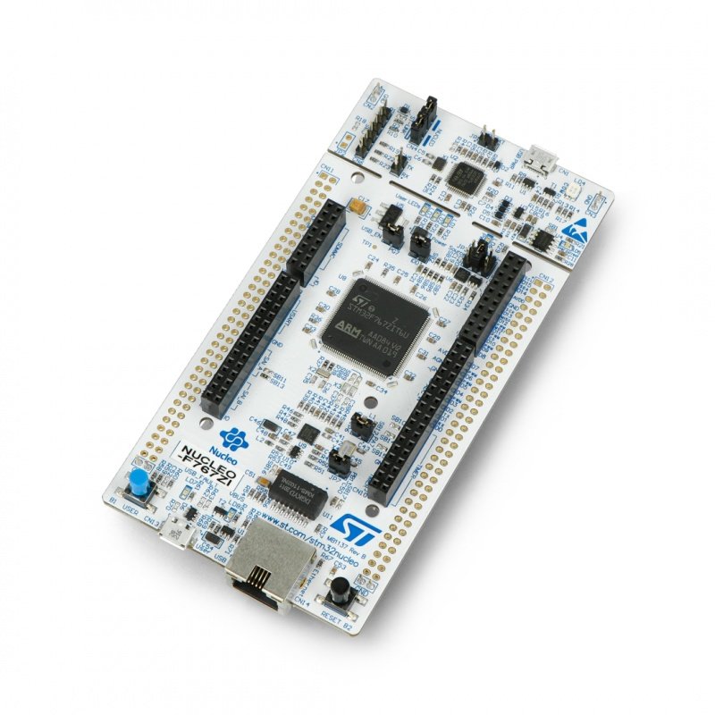
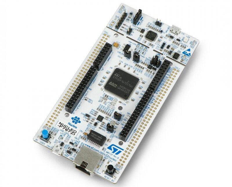
In this new guide series, we shall start developing peripheral for ARM Cortex M7 based MCU with STM32F7 specially STM32F767Zi Nucelo-144.
In this guide, we will cover the following:
- Getting the documents
- Developing bare metal GPIO output
- Demo
1. Getting the Documents:
In this guide and the upcoming guides, will need the following three documents
- STM32F767 Datasheet
- STM32F767 Reference Manual
- Nucleo-144 User Manual
You can search google for those files or simply get them from here:
Follow this link to see how to download, install, install FPU and start new project using keil uVision (link).
2. Developing Bare Metal GPIO Output:
STM32F767 Nucleo-144 has three user LEDs which they are Green, Red and Blue LEDs.
In order to turn on/off one of them we need to figure out which pins those LED are connected to, from Nucleo-144 user manual, LED section (6.5) , we can get the LED pins which they are the following:
| LED Colour | Pin |
| Green | PB0 |
| Blue | PB7 |
| Red | PB14 |
In this experiment, we shall use the blue LED which is connected to PB7.
Before we start don’t forget to add the chip header as following:
#include "stm32f7xx.h"
To star of, we need to enable clock access to GPIO B. To enable clock access, we need to find which bus is the GPIOB is connected to. We can find this from figure 2 from the datasheet.
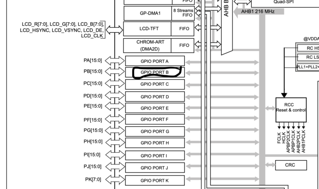
From the figure, GPIOB is connected to AHB1. To enable peripherals clock connected to AHB1, we need to go to the reference manual and see AHB1ENR register.
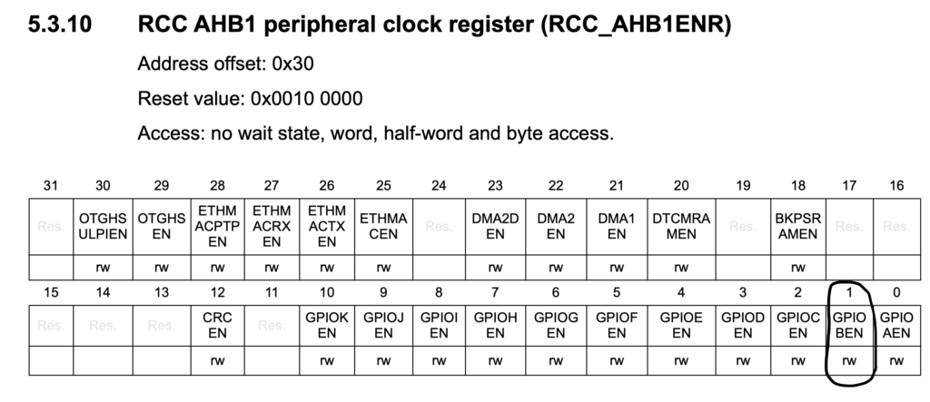
From the register, we see that bit 1 is responsible to enable clock access for GPIOB. Hence we can use CMSIS macro offered by STMicroelectronics to enable clock access as following:
RCC->AHB1ENR|=RCC_AHB1ENR_GPIOBEN;
After we enabled clock access to GPIOB, we need to configure PB7 as output, we head to GPIO section of reference manual and the MODER register to configure the pin.
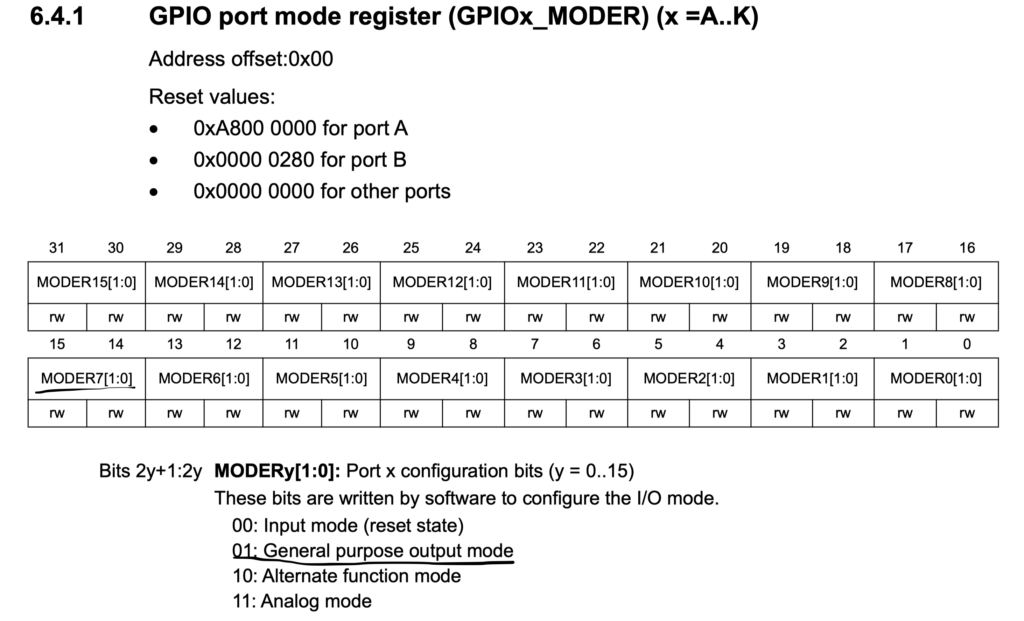
As seen from the register, we can set pin 7 as output as following:
- Set bit 14 to 1
- Reset bit 15 to 0
We can do this as following:
//set PB7 as output
	GPIOB->MODER|=GPIO_MODER_MODER7_0;
	GPIOB->MODER&=~GPIO_MODER_MODER7_1;
Now, after we configured the pin as output, we start our while(1) loop.
In the while loop, we set the pin to 1.
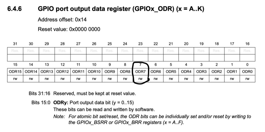
From the output data register, we can set bit 7 to 1 to turn on the LED and 0 to turn off the LED.
We can turn on the LED as following
GPIOB->ODR|=GPIO_ODR_OD7;
Wait a little bit of time using for loop as following
for (volatile int i=0;i<1000000;i++);
After the loop, set the PB7 back to zero as following
GPIOB->ODR&=~GPIO_ODR_OD7;
And wait again
for (volatile int i=0;i<1000000;i++);
Hence, the entire code shall be something like this:
#include "stm32f7xx.h"                  // Device header

int main(void)
	{
	//enable clock access to GPIOB
	RCC->AHB1ENR|=RCC_AHB1ENR_GPIOBEN;
	//set PB7 as output
	GPIOB->MODER|=GPIO_MODER_MODER7_0;
	GPIOB->MODER&=~GPIO_MODER_MODER7_1;

	while(1)
		{
		//set PB7 to high
		GPIOB->ODR|=GPIO_ODR_OD7;
		//delay for a little bit
		for (volatile int i=0;i<1000000;i++);
		//set PB7 back to zero
		GPIOB->ODR&=~GPIO_ODR_OD7;
		//delay for a little bit
		for (volatile int i=0;i<1000000;i++);
		}


	}
Add Comment