
In the previous guide on OLED (here), we took a look at how to connect SSD1306 I2C OLED with STM32F4. In this guide, we shall use the SPI version of the display to display text and picture.
In this guide, we shall cover the following:
- SSD1306 OLED display.
- Interface with STM32F4.
- SPI driver of SSD1306.
- Write Data, Command and Multidata
- Initializing sequence.
- Basic function to display text.
- Demo.
1. SSD1306 OLED Display:
Do you want to give a perfect look to your microcontroller project which traditional liquid crystal displays (LCDs) do not promise? In this case, OLED displays will be the best choice for you. Because they offer a good view angle and pixel density which makes it the perfect choice for graphics display projects at low cost.
SSD1306 OLED Types
There are different types of OLED displays available in the market. But the common thing in most displays is the SSD1306 CMOS OLED driver controller. The main component of OLED is an SSD1306 controller which is used to communicate with microcontrollers, such as TM4C123 Tiva Launchpad or STM32F4, using either SPI or I2C communication. But usually, I2C communication is preferred because it requires only two wires to communicate with STM32F411.
However, in this guide, we shall cover the SPI version.
I2C OLED Display
These displays come in different colors, sizes and shapes. In this tutorial, we will use an SPI based OLED display having size of 128×64 as shown in the figure below. But the good thing is programming doesn’t change much with the change of OLED size and color.
The following picture shows the pin wiring of the OLED display. As you can see from its pinout diagram, it consists of six pins such as Vcc, GND, CLK, MOSI,CS and DC. Vcc and GND pins are used to power OLED displays and the operating voltage range is between 3.3-5V. That means we can easily power it from the same source and connect directly with microcontrollers.
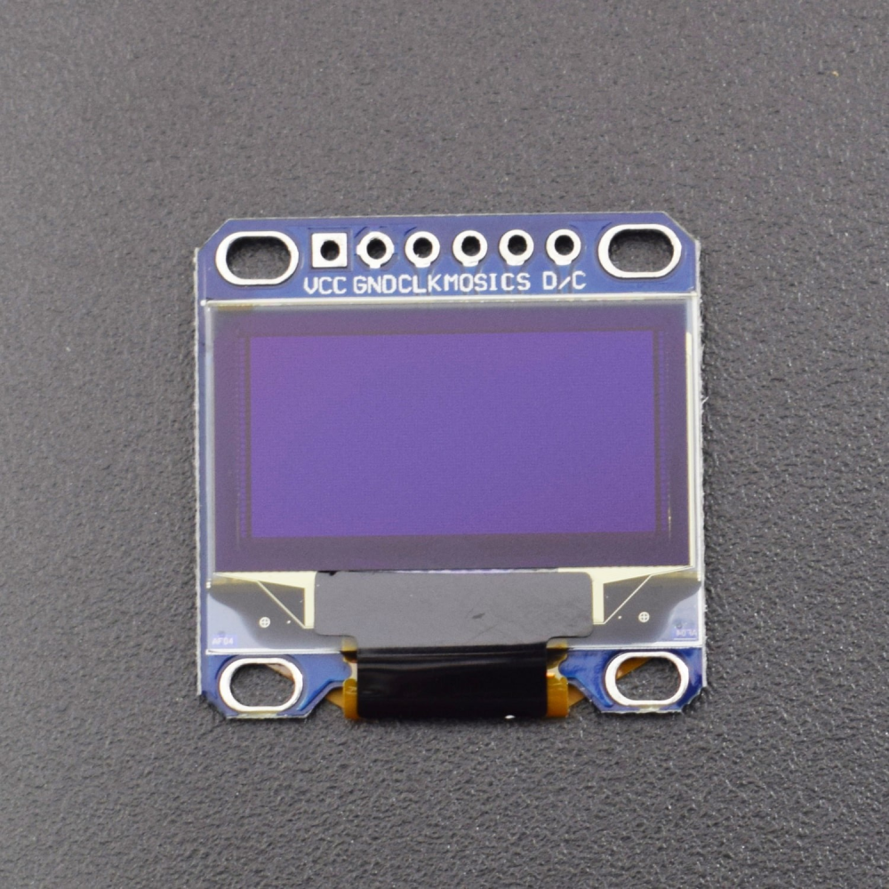
The pins description as following:
| OLED Pins | Meaning |
| Vcc | +Ve power source (3.3 to 5V) |
| GND | -Ve power source |
| CLK | Serial Clock of the SPI |
| MOSI | Master Out Slave of SPI |
| CS | Chip Select |
| D/C | Data/Command select |
2. Interface With STM32F4:
The interface as following:
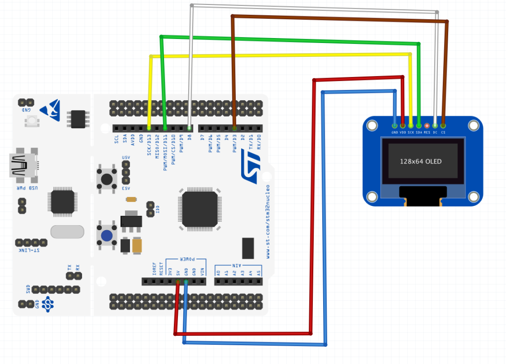
| SSD1306 SPI | STM32F411-Nucleo64 |
| Vcc | 5V |
| GND | GND |
| CLK | D13 (PA5) |
| MOSI | D11 (PA7) |
| CS | D8 (PA9) |
| DC | D4 (PA10) |
3. SPI driver for SSD1306:
Since the display is using SPI, we shall use SPI for that purpose. For more information about SPI, please refer to this guide here.
The GPIO initializing function:
void OLED_SPI_Pins_Init()
{
	RCC->AHB1ENR|=RCC_AHB1ENR_GPIOAEN; //enable clock for GPIOA

	//set PA5, PA6 and PA7 to alternate function mode
	GPIOA->MODER|=GPIO_MODER_MODE5_1|GPIO_MODER_MODE6_1|GPIO_MODER_MODE7_1;
	GPIOA->MODER &=~(GPIO_MODER_MODE5_0|GPIO_MODER_MODE6_0|GPIO_MODER_MODE7_0);

	//Set PA9 and PA10 as Output
	GPIOA->MODER|=GPIO_MODER_MODE9_0|GPIO_MODER_MODE10_0;
	GPIOA->MODER&=~(GPIO_MODER_MODE9_1|GPIO_MODER_MODE10_1);

	/*select which AF for PA5, PA6 and PA7*/
	GPIOA->AFR[0]|=(0x05<<20)|(0x05<<24)|(0x05<<28);
}
SPI Initializing:
void OLED_SPI_Configure()
{
	/*Enable clock access to SPI1 module*/
		RCC->APB2ENR |= RCC_APB2ENR_SPI1EN;

		/*Set clock to fPCLK/2*/
		SPI1->CR1 &=~(1U<<3);
		SPI1->CR1 &=~(1U<<4);
		SPI1->CR1 &=~(1U<<5);

		/*Enable full duplex*/
		SPI1->CR1 &=~(1U<<10);

		/*Set MSB first*/
		SPI1->CR1 &= ~(1U<<7);

		/*Set mode to MASTER*/
		SPI1->CR1 |= (1U<<2);

		/*Set 8 bit data mode*/
		SPI1->CR1 &= ~(1U<<11);

		/*Select software slave management by
		 * setting SSM=1 and SSI=1*/
		SPI1->CR1 |= (1<<8);
		SPI1->CR1 |= (1<<9);

		/*Enable SPI module*/
		SPI1->CR1 |= (1<<6);
}
SPI Write function for OLED:
void OLED_SPI_Write(char *data,uint32_t size)
{
	uint32_t i=0;

	while(i<size)
	{
		/*Wait until TXE is set*/
		while(!(SPI1->SR & (SPI_SR_TXE))){}

		/*Write the data to the data register*/
		SPI1->DR =(uint8_t) data[i];
		i++;
	}
	/*Wait until TXE is set*/
	while(!(SPI1->SR & (SPI_SR_TXE))){}

	/*Wait for BUSY flag to reset*/
	while((SPI1->SR & (SPI_SR_BSY))){}

	/*Clear OVR flag*/
	(void)SPI1->DR;
	(void)SPI1->SR;
}
Chip select and deselect:
void OLED_Select(void)
{
	GPIOA->BSRR =GPIO_BSRR_BR9;

}

/*Pull high to disable*/
void OLED_Deselect(void)
{
	GPIOA->BSRR =GPIO_BSRR_BS9;
}
Data/Command toggle:
void OLED_DataMode()
{
	GPIOA->BSRR=GPIO_BSRR_BS10;
}

void OLED_CommMode()
{
	GPIOA->BSRR=GPIO_BSRR_BR10;
}
Thats all for the SPI section.
4. Write Data, Command and Multidata:
In order to write data, we need to set D/C pin to high, set CS pin to low, write data and then set CS high as following:
void SSD1306_WRITEDATA(char command)
{
	OLED_DataMode();
	OLED_Select();
	OLED_SPI_Write(&command,1);
	OLED_Deselect();
}
To write command, same procedure as writing data. However, we need to set D/C to low as following:
void SSD1306_WRITECOMMAND(char command)
{
	OLED_CommMode();
	OLED_Select();
	OLED_SPI_Write(&command,1);
	OLED_Deselect();
}
To write multiple data when updating the display:
void SSD1306_Write_Multi_Data(char * data, uint16_t length)
{
	OLED_DataMode();
	OLED_Select();
	OLED_SPI_Write((char*)data,length);
	OLED_Deselect();

}
5. Initialization Sequence:
The initialization sequence as following:
uint8_t SSD1306_Init(void)
{
	 OLED_SPI_Pins_Init();

	 OLED_SPI_Configure();
	/* A little delay */
	uint32_t p = 2500;
	while(p>0)
		p--;

	/* Init LCD */
	SSD1306_WRITECOMMAND(0xAE); //display off
	SSD1306_WRITECOMMAND(0x20); //Set Memory Addressing Mode
	SSD1306_WRITECOMMAND(0x10); //00,Horizontal Addressing Mode;01,Vertical Addressing Mode;10,Page Addressing Mode (RESET);11,Invalid
	SSD1306_WRITECOMMAND(0xB0); //Set Page Start Address for Page Addressing Mode,0-7
	SSD1306_WRITECOMMAND(0xC8); //Set COM Output Scan Direction
	SSD1306_WRITECOMMAND(0x00); //---set low column address
	SSD1306_WRITECOMMAND(0x10); //---set high column address
	SSD1306_WRITECOMMAND(0x40); //--set start line address
	SSD1306_WRITECOMMAND(0x81); //--set contrast control register
	SSD1306_WRITECOMMAND(0xFF);
	SSD1306_WRITECOMMAND(0xA1); //--set segment re-map 0 to 127
	SSD1306_WRITECOMMAND(0xA6); //--set normal display
	SSD1306_WRITECOMMAND(0xA8); //--set multiplex ratio(1 to 64)
	SSD1306_WRITECOMMAND(0x3F); //
	SSD1306_WRITECOMMAND(0xA4); //0xa4,Output follows RAM content;0xa5,Output ignores RAM content
	SSD1306_WRITECOMMAND(0xD3); //-set display offset
	SSD1306_WRITECOMMAND(0x00); //-not offset
	SSD1306_WRITECOMMAND(0xD5); //--set display clock divide ratio/oscillator frequency
	SSD1306_WRITECOMMAND(0xF0); //--set divide ratio
	SSD1306_WRITECOMMAND(0xD9); //--set pre-charge period
	SSD1306_WRITECOMMAND(0x22); //
	SSD1306_WRITECOMMAND(0xDA); //--set com pins hardware configuration
	SSD1306_WRITECOMMAND(0x12);
	SSD1306_WRITECOMMAND(0xDB); //--set vcomh
	SSD1306_WRITECOMMAND(0x20); //0x20,0.77xVcc
	SSD1306_WRITECOMMAND(0x8D); //--set DC-DC enable
	SSD1306_WRITECOMMAND(0x14); //
	SSD1306_WRITECOMMAND(0xAF); //--turn on SSD1306 panel


	SSD1306_WRITECOMMAND(SSD1306_DEACTIVATE_SCROLL);

	/* Clear screen */
	SSD1306_Fill(SSD1306_COLOR_BLACK);

	/* Update screen */
	SSD1306_UpdateScreen();

	/* Set default values */
	SSD1306.CurrentX = 0;
	SSD1306.CurrentY = 0;

	/* Initialized OK */
	SSD1306.Initialized = 1;

	/* Return OK */
	return 1;
}
6. Basic function to display text:
In order to display text, we need the following:
- Go to xy point:
oid SSD1306_GotoXY(uint16_t x, uint16_t y) {
	/* Set write pointers */
	SSD1306.CurrentX = x;
	SSD1306.CurrentY = y;
}- Put character into the buffer:
char SSD1306_Puts(char* str, FontDef_t* Font, SSD1306_COLOR_t color) {
	/* Write characters */
	while (*str) {
		/* Write character by character */
		if (SSD1306_Putc(*str, Font, color) != *str) {
			/* Return error */
			return *str;
		}

		/* Increase string pointer */
		str++;
	}

	/* Everything OK, zero should be returned */
	return *str;
}- Update the display:
void SSD1306_UpdateScreen(void) {
	uint8_t m;

	for (m = 0; m < 8; m++) {
		SSD1306_WRITECOMMAND(0xB0 + m);
		SSD1306_WRITECOMMAND(0x00);
		SSD1306_WRITECOMMAND(0x10);

		/* Write multi data */

		SSD1306_Write_Multi_Data(&SSD1306_Buffer[SSD1306_WIDTH * m], SSD1306_WIDTH);
	}
}
7. Code:
You may download the full source code from here:
8. Demo:
Happy coding 🙂
9 Comments
I did your project Working with STM32 and Displays: SSD1306 SPI OLED display but with Nucleo-F446RE and STM32F401 it does not work for me I spent a lot of time; I imported the project to stm32cubeide program. 2. Interface With STM32F4 schematic and the below pin details does not match.
The YouTube video the wiring looks different I do not know what I’ m doing wrong.
Which OLED are you using?
I am using OLED SPI 7 pin 1 = GND ,,2 = VCC, 3 = SCK, 4 = MOSI, 5 = RES, 6 = DC, 7 = CS purchased from AliExpress, I’ m able to build the project but when I downloaded to nucleo-F446RE the OLED display is dead black, I tested with Arduino uno it works fine. I connected the res pin to VCC or GND still display is not ON, I have used a debug the code looks fine.
Without knowing more information like chip driver etc, we won’t be able to solve the issue.
Where I can buy a SSD1306 OLED SPI compatible with your code like the one show on the picture 6 pin oled
https://www.amazon.com/Hailege-SSD1306-Display-Arduino-Raspberry/dp/B08D7DVN3P
Original 0.96″ OLED SPI module 128X64 7 pin work fine with Arduino Uno
/* Set default values */
SSD1306.CurrentX = 0;
SSD1306.CurrentY = 0;
/* Initialized OK */
SSD1306.Initialized = 1;
At this part, Error display ( ‘SSD1306’ undeclared (first use in this function); did you mean ‘SSD1306_H’? ) .
How can I fix it?
Hi,
download the source code.
Add Comment