
In the previous guide (here), we took a look how to configure the I2S peripheral of STM32G070 and send the data using polling mode. In this guide, we shall use DMA to transmit the data.
In this guide, we shall cover the following:
- Enabling the DMA and configuration.
- Developing the driver.
- Results.
1. Enabling the DMA:
Continue from the previous guide:
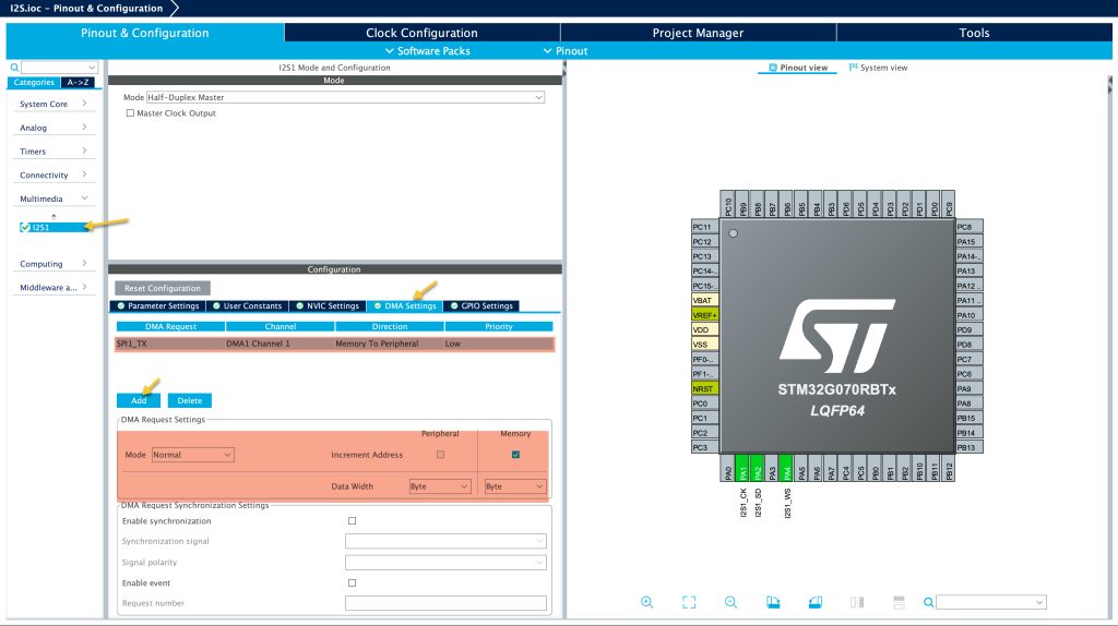
From multimedia, select I2S:
From the I2S select DMA settings, then click on add. Select any DMA Stream available and keep the settings as is. Feel free to select circular mode in case you want to keep streaming same data over and over.
Next, from NVIC settings, enable SPI global interrupt as following:
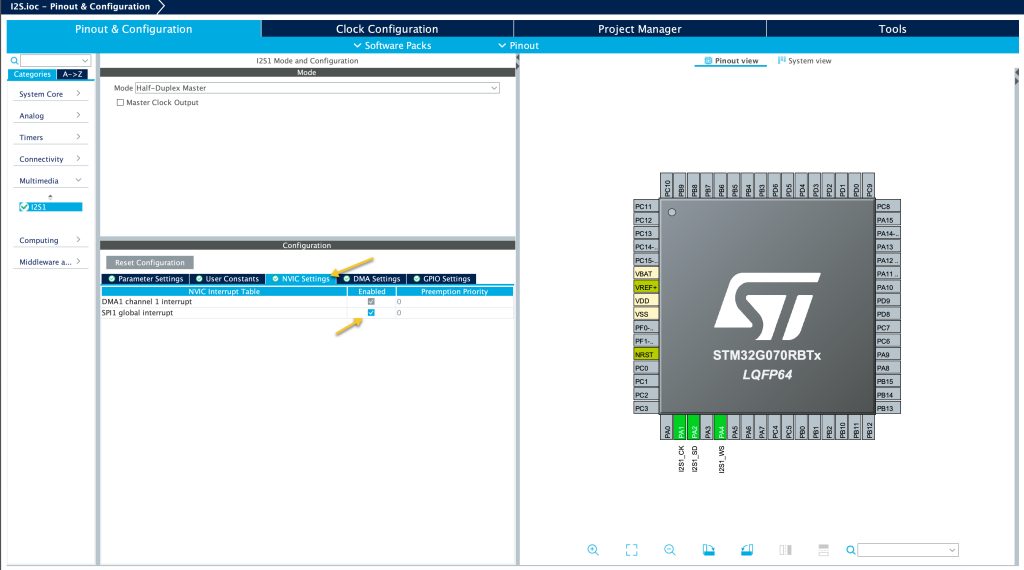
Save the project and this will generate the required codes.
2. Driver Development:
In main.c file:
In user begin PV section of the main.c file, declare the following the variable as volatile since this will be modified in the interrupt handler:
volatile uint8_t done=0;
In user code begin 3 in while loop of main function:
Transmit the data over I2S using DMA as following:
HAL_I2S_Transmit_DMA(&hi2s1, i2s_data, 10);
The function tasks the following parameters:
- Pointer to i2s handler which is hi2s1 in this case.
- Data buffer to be transmitted, which i2s_data in the case.
- Size of the data.
You notice that there is no timeout since this will be handled by the DMA and no need to use timeout.
Next, wait for the done to be 1 as following:
while(done==0);
Here, we are just waiting until the data has been transmitted.
Next, set done back to 0 as following:
done=0;
Wait 10 ms before starting again:
HAL_Delay(10);
Next, in user code begin 4, this function shall be called every time when I2S finishes transferring the data using DMA.
The function as following:
void HAL_I2S_TxCpltCallback(I2S_HandleTypeDef *hi2s)
{
	done=1;
}
Within the function, set done to 1.
Thats all for the driver development.
Save the project build the project and run it:

3. Results:
Connect logic analyzer to the pin and set the decoding mode to i2s and you should get this:

Happy coding 😉
Add Comment