In this guide, we shall use registers to change the core frequency from default 16MHz to 216MHz (maximum for F767ZIT).
We shall use CubeMX to determine the values required to reach the 216MHz operation.
1. Getting required settings from CubeMX
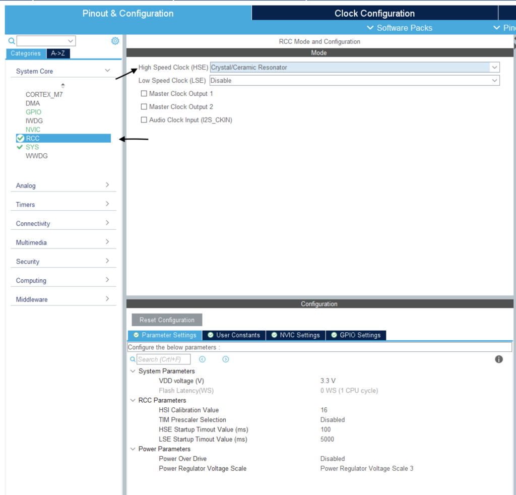
We start off by opening CubeMX and select your F7 chip (F767ZITx in my case).
After that, select system core then RCC and set the High Speed Clock as Crystal/Ceramic Resonator
After that, open Clock Configuration tab and follow the following steps
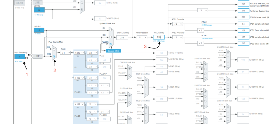
- 1. Set the crystal frequency to match yours (8MHz in my case)
- 2. Select HSE as PLL source MUX
- 3. Set HCLK to 216 and hit enter
Now write down the PLL_N, PLL_M and PLL_P values and also AHB1, APB1 and APB2 prescalers. In my case, I have those values:
#define PLL_M      4
#define PLL_N      216
#define PLL_P      2
After that head back to RCC and note the flash latency:
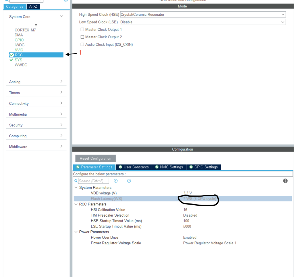
In my case, I need to flash latency to 7WS (8-CPU cycle).
2. Start configuring the clock
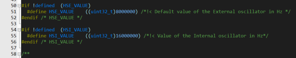
We start off by opening the project and open system_stm32f7xx.c file
In line HSE_VALUE change the value from 25000000 to the one match match yours (8000000 in my case)
Now, in main file we shall declare a function to change as following:
void SysClockConfig(void)
It takes not argument and returns nothing.
Inside the function we start defining the PLL_P, PLLM and PLL_N values
#define PLL_M      4
#define PLL_N      216
#define PLL_P      2
Now declare some variable to help us later
__IO uint32_t StartUpCounter = 0, HSEStatus = 0;
We start off by enabling external clock source as following:
RCC->CR |= ((uint32_t)RCC_CR_HSEON);
Then we wait until the clock is ready, if it is not ready within 3000 counts, break the function and jump to error section:
do
  {
    HSEStatus = RCC->CR & RCC_CR_HSERDY;
    StartUpCounter++;
  } while((HSEStatus == 0) && (StartUpCounter != 3000));
Check if the HSE is on
if ((RCC->CR & RCC_CR_HSERDY) != RESET)
  {
    HSEStatus = (uint32_t)0x01;
  }
  else
  {
    HSEStatus = (uint32_t)0x00;
  }
if activated, we continue configuring the clock
We start off by enabling clock access to power interface as following:
RCC->APB1ENR |= RCC_APB1ENR_PWREN;
Then we reset VOS which will force to mode three
PWR->CR1 &= (uint32_t)~(PWR_CR1_VOS);
Now we set the AHB1,APB1 and APB2 prescaler as following:
RCC->CFGR |= RCC_CFGR_HPRE_DIV1;


    RCC->CFGR |= RCC_CFGR_PPRE2_DIV2;


    RCC->CFGR |= RCC_CFGR_PPRE1_DIV4;
Then we configure the PLL as following:
RCC->PLLCFGR = PLL_M | (PLL_N << RCC_PLLCFGR_PLLN_Pos) | (((PLL_P >> 1) -1) << RCC_PLLCFGR_PLLP_Pos) |
                   (RCC_PLLCFGR_PLLSRC_HSE);
Now, we turn on the PLL and wait until it is on
RCC->CR |= RCC_CR_PLLON;


    while((RCC->CR & RCC_CR_PLLRDY) == 0)
    {
    }
Then we configure the flash latency to be 7WS (waiting state)
/* Configure Flash prefetch, Instruction cache, Data cache and wait state */
    FLASH->ACR = FLASH_ACR_LATENCY_7WS;
We select the PLL as clock source
  /* Select the main PLL as system clock source */
    RCC->CFGR &= (uint32_t)((uint32_t)~(RCC_CFGR_SW));
    RCC->CFGR |= RCC_CFGR_SW_PLL;

    /* Wait till the main PLL is used as system clock source */
    while ((RCC->CFGR & (uint32_t)RCC_CFGR_SWS ) != RCC_CFGR_SWS_PLL)
    {;}
Hence, the full code as following:
void SysClockConfig(void) //set the core frequency to 216MHz
{
#define PLL_M      4
#define PLL_N      216
#define PLL_P      2

__IO uint32_t StartUpCounter = 0, HSEStatus = 0;


  RCC->CR |= ((uint32_t)RCC_CR_HSEON);


  do
  {
    HSEStatus = RCC->CR & RCC_CR_HSERDY;
    StartUpCounter++;
  } while((HSEStatus == 0) && (StartUpCounter != 3000));

  if ((RCC->CR & RCC_CR_HSERDY) != RESET)
  {
    HSEStatus = (uint32_t)0x01;
  }
  else
  {
    HSEStatus = (uint32_t)0x00;
  }

  if (HSEStatus == (uint32_t)0x01)
  {

    RCC->APB1ENR |= RCC_APB1ENR_PWREN;
    PWR->CR1 &= (uint32_t)~(PWR_CR1_VOS);


    RCC->CFGR |= RCC_CFGR_HPRE_DIV1;


    RCC->CFGR |= RCC_CFGR_PPRE2_DIV2;


    RCC->CFGR |= RCC_CFGR_PPRE1_DIV4;


    RCC->PLLCFGR = PLL_M | (PLL_N << RCC_PLLCFGR_PLLN_Pos) | (((PLL_P >> 1) -1) << RCC_PLLCFGR_PLLP_Pos) |
                   (RCC_PLLCFGR_PLLSRC_HSE);


    RCC->CR |= RCC_CR_PLLON;


    while((RCC->CR & RCC_CR_PLLRDY) == 0)
    {
    }

    /* Configure Flash prefetch, Instruction cache, Data cache and wait state */
    FLASH->ACR = FLASH_ACR_LATENCY_7WS;

    /* Select the main PLL as system clock source */
    RCC->CFGR &= (uint32_t)((uint32_t)~(RCC_CFGR_SW));
    RCC->CFGR |= RCC_CFGR_SW_PLL;

    /* Wait till the main PLL is used as system clock source */
    while ((RCC->CFGR & (uint32_t)RCC_CFGR_SWS ) != RCC_CFGR_SWS_PLL)
    {;}
  }
  else
  { /* If HSE fails to start-up, the application will have wrong clock
         configuration. User can add here some code to deal with this error */
  }

	SystemCoreClockUpdate();


}
3. Validating Core Frequency:
In order to validate the core frequency, we shall use SysTick timer to generate interrupt at rate of 1KHz (each 1 millisecond) and enable clock to PORTA and set PA5 as output as following:
__disable_irq();

	SysTick->LOAD=216000-1;
	SysTick->VAL=0;
	SysTick->CTRL=7; //0b00000111;
	RCC->AHB1ENR |=RCC_AHB1ENR_GPIOAEN;
	GPIOA->MODER|= GPIO_MODER_MODER5_0; //PA5 as output
	__enable_irq();
in interrupt handler, we shall toggle PA5 as following:
void SysTick_Handler(void){
GPIOA->ODR^=GPIO_ODR_OD5;
}
After compile and upload the code and probe PA5 we shall get the following:
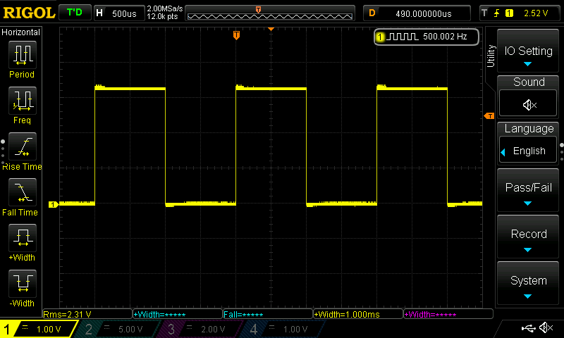
Since each division of the horizontal line is 500microseconds, and we are getting 2 division high and two division low, thats mean the on time 1 millisecond and 1 millisecond off which as we set it. Thats mean we successfully changed the core frequency from 16MHz to 216MHz. Now, you can get the full potential of your mcu.
Happy coding
9 Comments
Hello! “”We start off by opening the project and open system_stm32f7xx.c file””
So, I can see this file only if I generate my project with HAL library if I create empty project there is no such file in my project
Hi,
you need to include CMSIS and device to CubeIDE manually.
Thanks for this quick response. Indeed I need. I included my CMSIS in includes and symbols following STM32F7 Bare-Metal Programming From Ground Up instructions. I see we didn’t add a source file in our projects. Should system_stm32f7xx.c file be in Src folder?
you will find in source file.
Also, it is not necessary in CubeIDE, not like Keil uvision.
So, I might not change HSE_VALUE and follow the next instructions? Because there’s no such file and I can’t add it properly atm lol. Thank you a lot man, really appreciate what you do
Hi, i am confused by the command to wait for the PLL to enable. The reference manual (p. 131 & p. 137) sais that the PLLRDY bit is cleared once the PLL is ready. Your code waits until the bit is 1 to proceed…
Here, when the PLL is not ready, it means it has not yet reached the required speed. Hence, we shall wait for the PLL to be locked or ready.
It needs time between enabling the PLL and reaching the required frequency. Usually few microseconds but we must wait wait for it before switching the system to use PLL just to ensure everything is working properly.
omg, its actually first time i see someone giving 2MHz to the vcoIN, as it is recommended by the reference manual:
“it is recommended to select a frequency of 2 MHz to limit PLL jitter.” rm0410Rev5 inkPage 168of1942
I dont get it y in every Example in that unnecessarily giant cubef7 package, they always give 1MHz into vco
Hi,
the VCOin is already set to 2MHz.
My external clock is 8MHz divided by 4, you will get 2MHz.
Add Comment