In this third and final part guide on ModBus-RTU, we shall communication with ModBus enabled device.
In this guide, we shall cover the following:
- Device connection with MAX485.
- Sending and receiving data.
- Conde download.
- Results.
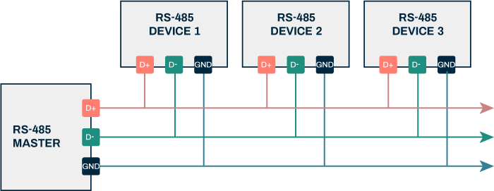
7. Device Connection with MAX485:
The connection of ModBus enabled device as following:
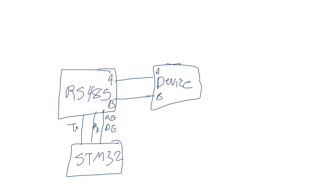
The connection as simple as connected A terminal to A of the device to A of the MAX485 and in similar manner for B.
Note: My device is operating from main voltage, if you don’t know how to handle this, please use other device that uses different low voltage.
8. Sending and Receiving Data:
The device uses standard 8byte to be transmitted as explained in the previous guide.
However, when receiving the data, the data structure as following:
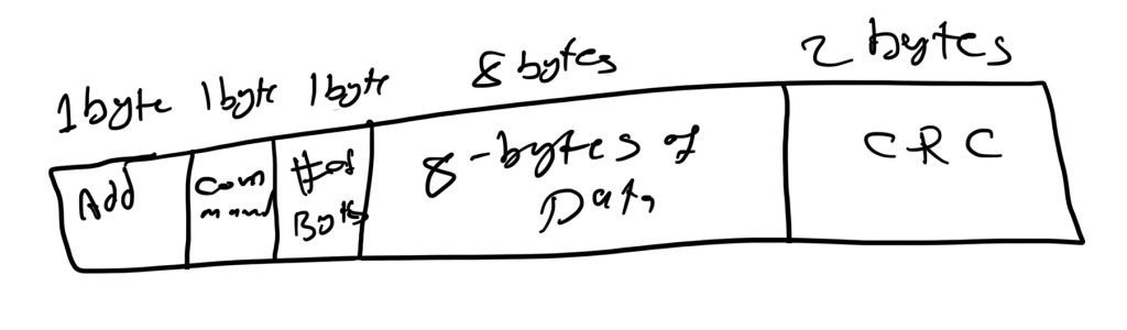
- 1st byte for the device address.
- Second byte for the command.
- Third byte represents number of bytes to be send and the rest are zero.
- From byte 4 to byte 11 are the data.
- bye 12 and 13 is for CRC.
In main.c source. We start with including the following header files:
#include "delay.h"
#include "uart1.h"
#include "MAX485.h"
From the setup of the device, the address is 1. From the datasheet, the read command is 0x03 and to read Van is register 0x0018.Hence, we can declare it as following:
#define Addr 0x01
#define Read 0x03
#define VaR	 0x18
Declare the following datasize to hold the data to be read, which is 40 so we have enough space to receive all the data as following:
#define dataSize 40

uint8_t data[dataSize]={0};
Define a volatile to indicate that UART received all the data as following:
volatile uint8_t uartRxDone=0;
Float to store the read voltage from the device:
float volt;
The following function is convert 4 bytes of byte to float as following:
float bytes_to_float(uint8_t *data) {
    uint32_t int_rep = ((uint32_t)data[0] << 24) |
                       ((uint32_t)data[1] << 16) |
                       ((uint32_t)data[2] << 8) |
                       (uint32_t)data[3];
    return *(float*)&int_rep;
}
In main function:
	Delay_Init(16000000);
	MAX485_RE_DE_Init();
	SetRS485Mode(Receiver);
	UART1_Pins_Init();
	UART1_Init();
	Delay(10);
	UART1_DMA_RX_Until_IDLE(data,dataSize);
Intialize the delay with frequency of 16MHz (default for STM32F4xx).
Initialize the RE/DE pin.
Set the MAX485 into receiver mode.
Initialize the UART1 by initialization of pins first then the UART peripheral.
delay for 10ms for stability.
Enable the RX in DMA with IDLE line detection.
In while 1 loop:
		Delay(10);
		RS485SendData(Addr,Read,VaR,4);
		while(uartRxDone==0);
		uartRxDone=0;
Wait for 10ms.
Send the request to read voltage.
Wait until the STM32 read the uart and get the voltage value.
Reset the uartRxDone to 0.
In UART_RX_Complete function:
void UART_RX_Complete(void)
{
	uartRxDone=1;
	volt=bytes_to_float(&data[3]);
	UART1_DMA_RX_Until_IDLE(data,dataSize);
}- Set the uartRxDone to 1.
- get the voltage values readying the four bytes starting from address 3.
- Launch the DMA again.
9. Results:
Build the project and start debugging session and add volt variable to live expression and start the code.
You should get the following results:

Which is the same as shown in the device:

Note: Due to the fluctuation in our main, the results are slightly different.
Happy coding 😉
2 Comments
I am impressed by your work on STM32 on registers. I like the entries about RS-485 and Modbus-RTu I count on the next entries from this series, e.g. on some specific example. The topic is very interesting to me. Regards and waiting impatiently …
This is the last part about modbus.
Add Comment