In the previous guide (here), we have successfully initialized the LCD and filled the screen the color. In this guide, we shall take a look at the touch controller, it’s features and initialize the required peripherals.
In this guide, we shall cover the following:
- STMPE811 Features.
- STMPE811 Connection with STM32F429.
- I2C Initializations.
- Interrupt Initialization.
1. STMPE811 Features:
8 GPIOs
■ 1.8 – 3.3 V operating voltage
■ Integrated 4-wire touchscreen controller
■ Interrupt output pin
■ Wakeup feature on each I/O
2 ■ SPI and I C interface
■ Up to 2 devices sharing the same bus in I 2 C mode (1 address line)
■ 8-input 12-bit ADC
■ 128-depth buffer touchscreen controller
■ Touchscreen movement detection algorithm
■ 25 kV air-gap ESD protection (system level)
■ 4 kV HBM ESD protection (device level)
Applications
■ Portable media players
■ Game consoles
■ Mobile and smartphones
■ GPS
The STMPE811 is a GPIO (general purpose input/output) port expander able to interface a main digital ASIC via the two-line bidirectional bus (I 2 C). A separate GPIO expander is often used in mobile multimedia platforms to solve the problems of the limited amount of GPIOs typically available on the digital engine.
The STMPE811 offers great flexibility, as each I/O can be configured as input, output or specific functions. The device has been designed with very low quiescent current and includes a wakeup feature for each I/O, to optimize the power consumption of the device.
A 4-wire touchscreen controller is built into the STMPE811. The touchscreen controller is enhanced with a movement tracking algorithm (to avoid excessive data), a 128 x 32 bit buffer and programmable active window feature.
Funcitonal Overview:

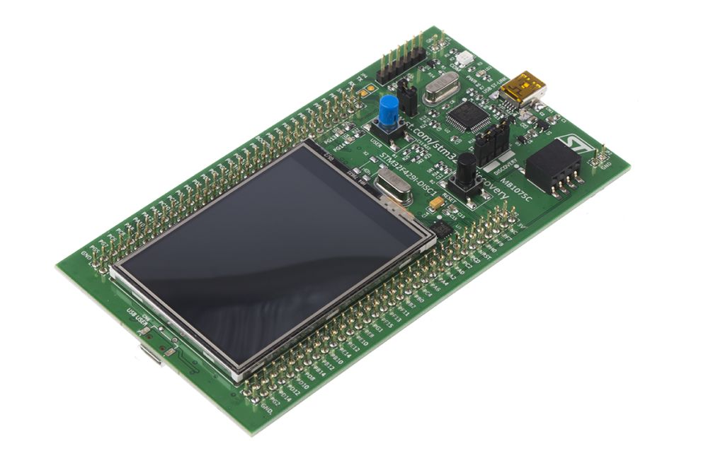
2. STMPE811 Connection with STM32F429:
From STM32F429-disco schematic documentation (MB1075), we can find the connection as following:

We can clearly see the connection with STM32F429 using I2C3 bus and we have touch interrupt output to indicate that there is a touch to the touch panel.
Also, the pullup resistors which is mandatory for i2c are present, correct 3V3 is supplied and connected to the touch panel pins.
Digging deeper, we can find exactly which pins as following:

| STM32F429 | STMPE811 |
| PA8 (I2C3 SCL) | SCLK |
| PC9 (I2C3 SDA) | SDATA |
| PA15 | INT (interrupt) |
3. I2C Initialization:
Since the touch controller is connected to I2C3, we shall initialize I2C3.
You may refer to this guide for how to initialize the I2C.
Create new header file with name of i2c3.h
The content of the header file:
#ifndef I2C3_H_
#define I2C3_H_

#include "stdint.h"

void i2c3_init(void);
void I2C3_WriteByte(uint8_t saddr,uint8_t maddr, uint8_t *data);
void I2C3_ReadMultiByte(uint8_t saddr,uint8_t maddr, uint8_t* data, uint16_t n);

#endif /* I2C3_H_ */
Create new source file with name of i2c3.c.
The content of the source file:
#include "STM32F4xx.h"

#include "i2c3.h"


#define AF04 0x04

void i2c3_init(void)
{
	/*GPIO Configuration*/

	/*Enable Clock access to GPIOA and GPIOC*/
	RCC->AHB1ENR|=RCC_AHB1ENR_GPIOAEN|RCC_AHB1ENR_GPIOCEN;

	/*GPIOA configuration*/
	GPIOA->MODER|=GPIO_MODER_MODE8_1;
	GPIOA->MODER&=~GPIO_MODER_MODE8_0;

	GPIOA->OTYPER|=GPIO_OTYPER_OT8;

	GPIOA->AFR[1]|=(AF04<<GPIO_AFRH_AFSEL8_Pos);

	/*GPIOC configuration*/
	GPIOC->MODER|=GPIO_MODER_MODE9_1;
	GPIOC->MODER&=~GPIO_MODER_MODE9_0;

	GPIOC->OTYPER|=GPIO_OTYPER_OT9;

	GPIOC->AFR[1]|=(AF04<<GPIO_AFRH_AFSEL9_Pos);


	/*I2C3 Init*/

	RCC->APB1ENR|=RCC_APB1ENR_I2C3EN;

	I2C3->CR1=I2C_CR1_SWRST;//reset i2c
	I2C3->CR1&=~I2C_CR1_SWRST;// release reset i2c
	I2C3->CR2|=0x2d;//set clock source to 42MHz
	I2C3->CCR=0xe1 ;  //based on calculation
	I2C3->TRISE=0x2e; //output max rise
	I2C3->CR1|=I2C_CR1_PE; //enable I2C

}

void I2C3_WriteByte(uint8_t saddr,uint8_t maddr, uint8_t *data)
{
	while(I2C3->SR2&I2C_SR2_BUSY){;}          /*wait until bus not busy*/
	I2C3->CR1|=I2C_CR1_START;                 /*generate start*/
	while(!(I2C3->SR1&I2C_SR1_SB)){;}         /*wait until start bit is set*/
	I2C3->DR = saddr<< 1;                 	 /* Send slave address*/
	while(!(I2C3->SR1&I2C_SR1_ADDR)){;}      /*wait until address flag is set*/
	(void)I2C3->SR2; 							/*clear SR2 by reading it */
	while(!(I2C3->SR1&I2C_SR1_TXE)){;}       /*Wait until Data register empty*/
	I2C3->DR = maddr;                        /* send memory address*/
	while(!(I2C3->SR1&I2C_SR1_TXE)){;}       /*wait until data register empty*/
	I2C3->DR = *data;
	while (!(I2C3->SR1 & I2C_SR1_BTF));      /*wait until transfer finished*/
	I2C3->CR1 |=I2C_CR1_STOP;
}

void I2C3_ReadMultiByte(uint8_t saddr,uint8_t maddr, uint8_t* data, uint16_t n)
{
	while (I2C3->SR2 & I2C_SR2_BUSY){;}
	I2C3->CR1|=I2C_CR1_START;
	while(!(I2C3->SR1 & I2C_SR1_SB)){;}
	I2C3->DR=saddr<<1;
	while(!(I2C3->SR1 & I2C_SR1_ADDR)){;}
	(void)I2C3->SR2;
	while(!(I2C3->SR1&I2C_SR1_TXE)){;}
	I2C3->DR = maddr;
	while(!(I2C3->SR1&I2C_SR1_TXE)){;}
	I2C3->CR1|=I2C_CR1_START;
	while(!(I2C3->SR1 & I2C_SR1_SB)){;}
	I2C3->DR=saddr<<1|1;
	while(!(I2C3->SR1 & I2C_SR1_ADDR)){;}
	temp=I2C3->SR2;
	I2C3->CR1|=I2C_CR1_ACK;
	while(n>0U)
	{
		if(n==1U)
		{
			I2C3->CR1&=~I2C_CR1_ACK;
			I2C3->CR1|=I2C_CR1_STOP;
			while(!(I2C3->SR1&I2C_SR1_RXNE)){;}
			*data++=I2C3->DR;
			break;
		}
		else
		{
			while(!(I2C3->SR1&I2C_SR1_RXNE)){;}
			(*data++)=I2C3->DR;
			n--;

		}
	}
}
4. Interrupt Initialization:
To understand how to configure the EXTI, please refer to this guide.
Create new source file with name of EXTI.c.
In the source file:
#include "exti.h"

#include "stm32f4xx.h"

void PA15_EXTI_Init(void)
{

	__disable_irq();

	RCC->AHB1ENR|=RCC_AHB1ENR_GPIOAEN;

	GPIOA->MODER&=~GPIO_MODER_MODE15;

	RCC->APB2ENR|=RCC_APB2ENR_SYSCFGEN;

	SYSCFG->EXTICR[3]|=SYSCFG_EXTICR4_EXTI15_PA;

	EXTI->IMR |=EXTI_IMR_IM15;

	EXTI->RTSR |=EXTI_RTSR_TR15;

	NVIC_EnableIRQ(EXTI15_10_IRQn);

	__enable_irq();

}
Create new header file with name of EXTI.h.
In the header file:
#ifndef EXTI_H_
#define EXTI_H_

#include "stdint.h"

void PA15_EXTI_Init(void);


#endif /* EXTI_H_ */
In the second section, we shall handle the interrupt handler.
Stay tuned.
Happy coding 🙂
Add Comment