In this guide, we shall discuss what is I2C and how to make an i2c bus scanner to scan the slave devices that connected to the i2c1 bus of STM32F411
In this guide we will cover the following:
- What is I2C
- I2C setup for stm32f4
- I2C bus scanner code
- Results
1.1: What is I2C
I2C or Inter Integrated Circuit is type of synchronous serial communication that capable to communicate with up to 127 slave devices as show in figure below.
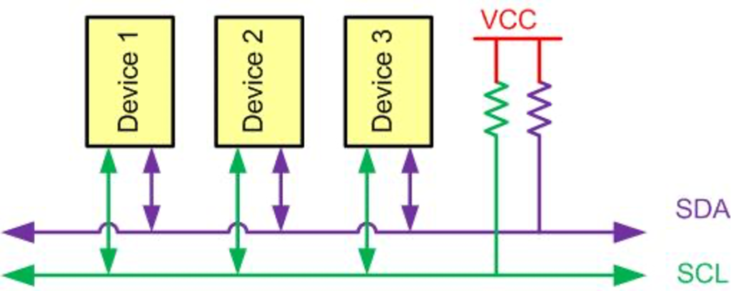
Like UART communication, I2C only uses two wires to transmit data between devices:
- SDA (Serial Data): The line for the master and slave to send and receive data.
- SCL (Serial Clock): The line that carries the clock signal.
1.2: HOW I2C WORKS
With I2C, data is transferred in messages. Messages are broken up into frames of data. Each message has an address frame that contains the binary address of the slave, and one or more data frames that contain the data being transmitted. The message also includes start and stop conditions, read/write bits, and ACK/NACK bits between each data frame:
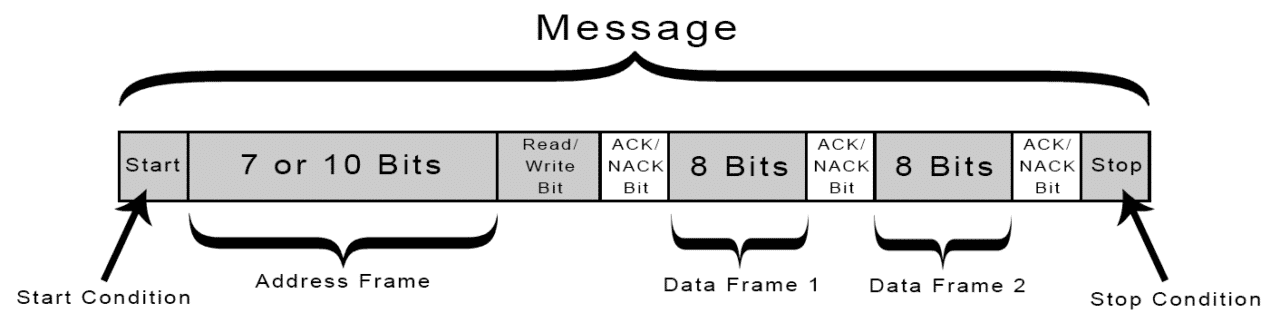
Start Condition: The SDA line switches from a high voltage level to a low voltage level before the SCL line switches from high to low.
Stop Condition: The SDA line switches from a low voltage level to a high voltage level after the SCL line switches from low to high.
Address Frame: A 7 or 10 bit sequence unique to each slave that identifies the slave when the master wants to talk to it.
Read/Write Bit: A single bit specifying whether the master is sending data to the slave (low voltage level) or requesting data from it (high voltage level).
ACK/NACK Bit: Each frame in a message is followed by an acknowledge/no-acknowledge bit. If an address frame or data frame was successfully received, an ACK bit is returned to the sender from the receiving device.
For more information and detailed explanations refer to this NXP documentation (here).
2.1: I2C setup for STM32F4: locating pins
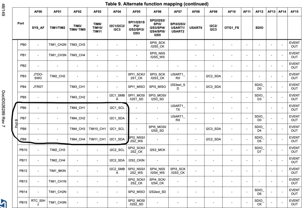
First we need to find which pins are for I2C1 bus.
From Table 9 of STM32F411 datasheet we find the pins for I2C1
Now We find which bus provides the clock to I2C1. This can be found in datasheet of STM32F411
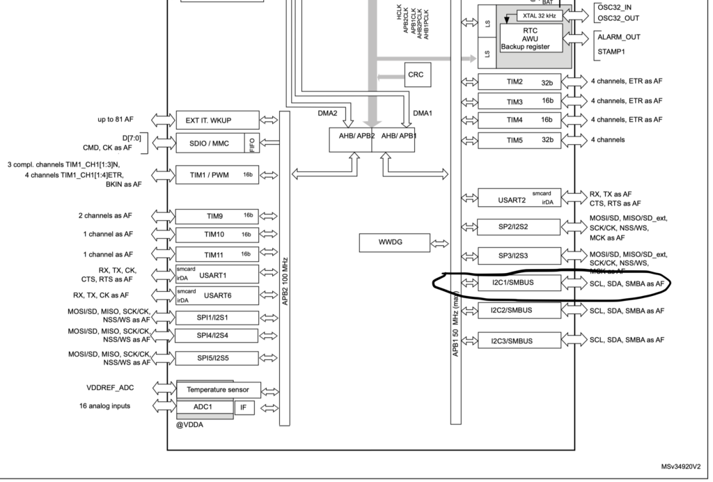
From the block diagram, the I2C1 is connected to APB1.
2.2: I2C setup for STM32F4: Configuration
Now We need to enable clock access to I2C1 and GPIOB as following:
RCC->AHB1ENR|=RCC_AHB1ENR_GPIOBEN; //enable gpiob clock
RCC->APB1ENR|=RCC_APB1ENR_I2C1EN; //enable i2c1 clock
Then configure the pins as alternate function and AF4:
GPIOB->MODER|=0xA0000; //set pb8and9 to alternative function
GPIOB->AFR[1]|=0x44;
Now we need to set the most important feature of I2C which the pins must be open drain as following
GPIOB->OTYPER|=GPIO_OTYPER_OT8|GPIO_OTYPER_OT9; //set pb8 and pb9 as open drain
Now we need to configure the I2C as following
I2C1->CR1=I2C_CR1_SWRST;//reset i2c
I2C1->CR1&=~I2C_CR1_SWRST;// release reset i2c
I2C1->CR2|=16;//set clock source to 16MHz
I2C1->CCR=80;  //based on calculation
I2C1->TRISE=17; //output max rise
I2C1->CR1|=I2C_CR1_PE; //enable I2C
Set up for I2C is completed.
2.3: I2C setup for STM32F4: I2C scan bus
void i2c_bus_scan(void)
{
					int a=0; //address variable
         for (uint8_t i=0;i<128;i++) //go through all 127 address
   {
            I2C1->CR1 |= I2C_CR1_START; //generate start
            while(!(I2C1->SR1 & I2C_SR1_SB)); // wait to start to be generated
            I2C1->DR=(i<<1|0); // transmit the address
            while(!(I2C1->SR1)|!(I2C1->SR2)){}; //clear status register
            I2C1->CR1 |= I2C_CR1_STOP; //generate stop condition
            delay(100);//minium wait time is 40 uS, but for sure, leave it 100 uS
            a=(I2C1->SR1&I2C_SR1_ADDR); //read the status register address set
            if (a==2)//if the address is valid
         {
					 //print the address
					 sprintf(data,"Found I2C device at adress 0x%X (hexadecimal), or %d (decimal)\r\n",i,i);
                UART_Write_String(data);
         }
     }
}
The UART_Write_String function can be obtained from here (link)
or
Simply download the entire project from here:
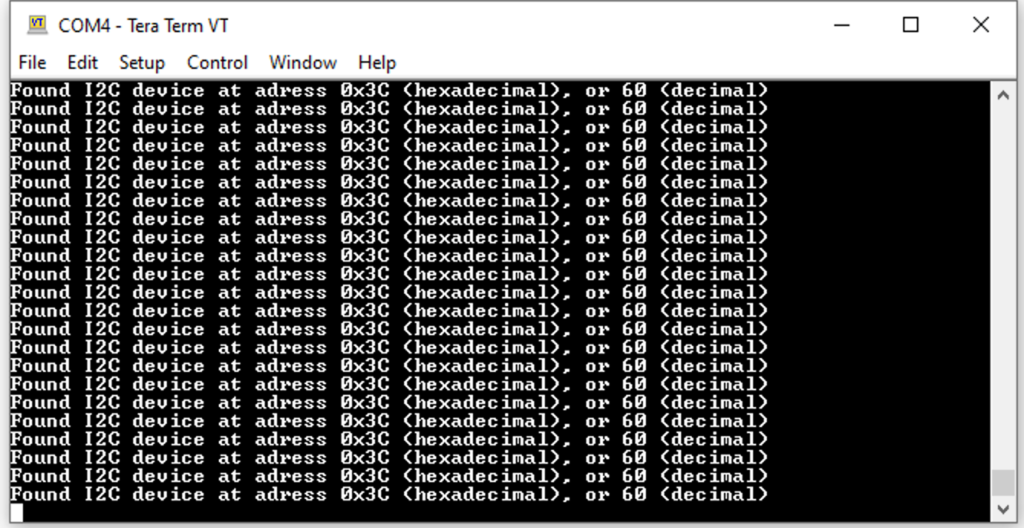
3. Results
Compile, upload the code and open your favourite terminal and you shall see the address of connected devices (Note: I got only 1 device connected)
Happy coding 🙂
Add Comment