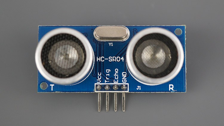
In the previous guide(here), we looked at the operation principle of how ultrasonic works and we used very crude code to measure the distance. In this guide, we shall use external GPIO interrupt and timer 2 of the STM32F4 to measure the distance.
In this guide, we will cover the following:
- External interrupt programming
- Timer configuration
- Measuring the distance
- Schematic
- Code
- Results
1. External interrupt programming
Before we head into the interrupt programming, for detailed interrupt guide, please read the following article from here (Link).
From the schematic, the trigger pin is connected to PA0 and echo pin to PA1. Hence we need to enable clock access to GPIOA (for details use the following article link).
//Enable clock access to GPIO A
	RCC->AHB1ENR|=RCC_AHB1ENR_GPIOAEN;
Then we need to enable clock access to SYSCFG.
//Enable clock access to System Configuration Control
	RCC->APB2ENR|=RCC_APB2ENR_SYSCFGEN;
Configure the PA0 as output and PA1 as input
//set PA0 to output
	GPIOA->MODER|=GPIO_MODER_MODE0_0;
	//Make sure that PA0 is low
	GPIOA->BSRR=GPIO_BSRR_BR_0;
	//Set PA1 to input
	GPIOA->MODER&=~(GPIO_MODER_MODE1_0|GPIO_MODER_MODE1_1);
Now, we enable interrupt for port A from SYSCFG external interrupt configuration register 1 as following:
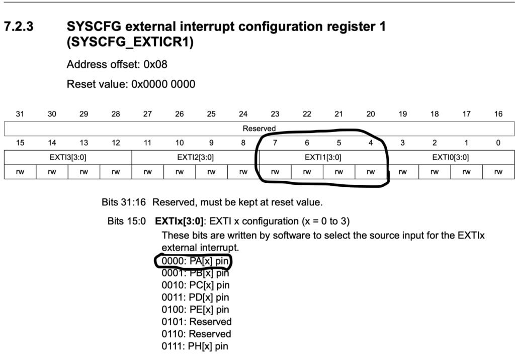
//Enable PA1 interrupt
	SYSCFG->EXTICR[0]|=SYSCFG_EXTICR1_EXTI1_PA;
Now, we need to unmask the interrupt for line1
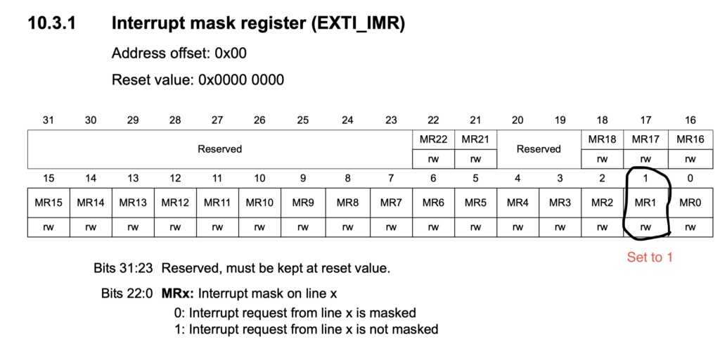
//unmask line 1
	EXTI->IMR|=EXTI_IMR_MR1;
Finally we enable External interrupt line 1 in NVIC as following:
NVIC_EnableIRQ(EXTI1_IRQn);
We have not yet select on which edge to trigger since we will change this during code exectution
2. Timer configuration:
In this guide, we shall use SysTick to generate delay in microseconds and TIM2 to measure the pulse length.
For more information about SysTick timer, you can read the following guide (here).
How to enable TIM2 you can use this guide (from here)
SysTick delay for microseconds delay
void delay_uS(int uS)
	{
	SysTick->LOAD=16-1;
	SysTick->VAL=0;
	SysTick->CTRL=0x5;
		for (int i=0;i<uS;i++)
		{
			while(!(SysTick->CTRL &0x10000)){}
		}
	SysTick->CTRL=0;
	}
Enable TIM2, set prescaler to 16-1 and ARR to 250000 and start the timer as following:
//Enable clock access to TIM2
	RCC->APB1ENR|=RCC_APB1ENR_TIM2EN;
	//set prescaler to 16-1 for 1MHz
	TIM2->PSC=16-1;
	//Set the ARR to 250000 (250 millis second max)
	TIM2->ARR=250000;
	//Enable Timer
	TIM2->CR1=TIM_CR1_CEN;
3.1 Measuring the distance:
We start of by setting PA0 to high for 10 microseconds, configure the interrupt to rising edge then setting the PA0 to low
	//set trigger pin to high
			GPIOA->BSRR=GPIO_BSRR_BS_0;
			//Set PA1 interrupt to Rising Edge
			EXTI->RTSR|=EXTI_RTSR_TR1;
			//delay for 10 microseconds
			delay_uS(10);
			// set trigger pin to low
			GPIOA->BSRR=GPIO_BSRR_BR_0;
we will wait until the sensor is finished
			//wait until finish is set
			while(finished==0){;}
Then we reset the finished back to 0 and start calculation the distance
//reset the finished value
			finished=0;
			//calculate the disatnce
			disatnce=((duration/2)/29.1);
Now we delay by half second as following
	//delay by half second
			delay_uS(500000);
3.2 Interrupt handling
first we check the direction if it is rising or falling edge as following
If yes, change the trigger to falling edge, reset timer2 counter and set direction to 1
if(dir==0)
				{
				EXTI->FTSR|=EXTI_FTSR_TR1;
				TIM2->CNT=0;
				dir=1;
				}
if not
This means the we are at the falling edge and we need to store the current timer value, set finished to 1 and dir back to zero
else
				{
				finished=1;
				duration=TIM2->CNT;
				dir=0;
				}
After that, we clear the interrupt pending flag as following
EXTI->PR=EXTI_PR_PR1;
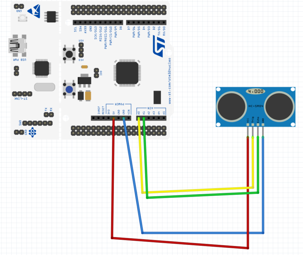
4. Schematics
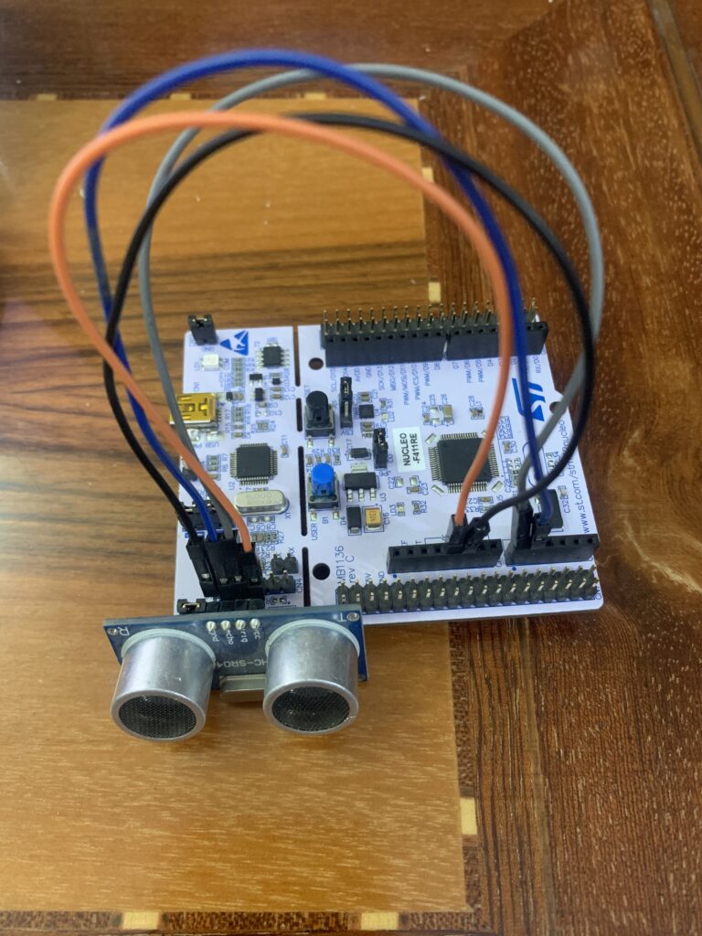
he wiring of HC-SR04 with STM32 is shown as below. The Vcc of the HC-SR04 is connected to the 5V of the Nucleo board, GND to GND of the Nucleo board, Trig to A0 (PA0) and echo to A1 (PA1).
5. Code:
Here is the entire code:
#include "stm32f4xx.h"                  // Device header

/*
pinout
TRIG of Ultrasonic to PA0
ECHO of Ultrasonic to PA1
*/

volatile int finished,duration,dir;
float disatnce;

void delay_uS(int uS)
	{
	SysTick->LOAD=16-1;
	SysTick->VAL=0;
	SysTick->CTRL=0x5;
		for (int i=0;i<uS;i++)
		{
			while(!(SysTick->CTRL &0x10000)){}
		}
	SysTick->CTRL=0;
	}


int main(void)
	{
	//Enable clock access to GPIO A
	RCC->AHB1ENR|=RCC_AHB1ENR_GPIOAEN;
	//Enable clock access to System Configuration Control
	RCC->APB2ENR|=RCC_APB2ENR_SYSCFGEN;
	//set PA0 to output
	GPIOA->MODER|=GPIO_MODER_MODE0_0;
	//Make sure that PA0 is low
	GPIOA->BSRR=GPIO_BSRR_BR_0;
	//Set PA1 to input
	GPIOA->MODER&=~(GPIO_MODER_MODE1_0|GPIO_MODER_MODE1_1);
	//Enable PA1 interrupt
	SYSCFG->EXTICR[0]|=SYSCFG_EXTICR1_EXTI1_PA;
	//unmask line 1
	EXTI->IMR|=EXTI_IMR_MR1;

	//Enable clock access to TIM2
	RCC->APB1ENR|=RCC_APB1ENR_TIM2EN;
	//set prescaler to 16-1 for 1MHz
	TIM2->PSC=16-1;
	//Set the ARR to 250000 (250 millis second max)
	TIM2->ARR=250000;
	//Enable Timer
	TIM2->CR1=TIM_CR1_CEN;


	NVIC_EnableIRQ(EXTI1_IRQn);


	while(1)
			{
			//set trigger pin to high
			GPIOA->BSRR=GPIO_BSRR_BS_0;
			//Set PA1 interrupt to Rising Edge
			EXTI->RTSR|=EXTI_RTSR_TR1;
			//delay for 10 microseconds
			delay_uS(10);
			// set trigger pin to low
			GPIOA->BSRR=GPIO_BSRR_BR_0;
			//wait until finish is set
			while(finished==0){;}
			//reset the finished value
			finished=0;
			//calculate the disatnce
			disatnce=((duration/2)/29.1);
			//delay by half second
			delay_uS(500000);
			}
	}


	void EXTI1_IRQHandler(void)
			{
			if(dir==0)
				{
				EXTI->FTSR|=EXTI_FTSR_TR1;
				TIM2->CNT=0;
				dir=1;
				}

			else
				{
				finished=1;
				duration=TIM2->CNT;
				dir=0;
				}

			EXTI->PR=EXTI_PR_PR1;
			}
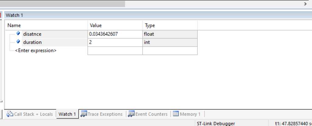
6. Results:
2 Comments
Hello again:) I’m trying to do this code work for stmf7 and when I get duration=2 I instantly get this:
this is the code that gets called when the processor receives an
* unexpected interrupt. This simply enters an infinite loop, preserving
* the system state for examination by a debugger.
What can be a reason? I messed up somewhere with interrupt registers?
p.s. I was stuck in infinite loop even in the first ultrasonic guide idk what I’m doing wrong. if I just toggle trig pin my Logic analyzer keeps showing me the correct signal.
Add Comment