In the previous guide (here), we took a look what is LvGL setup the environment. In this guide, we shall initialize the LCD and the touch.
In this guide, we shall cover the following:
- Display initialization.
- Touch Initialization.
1. Display Initialization:
Before we initialize the LCD and the touch, we need to find which pins are connected to the LCD and touch driver.
From the STM32F429-disco schematic, we can find the following:
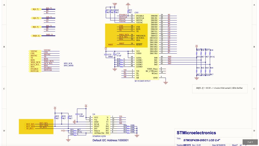
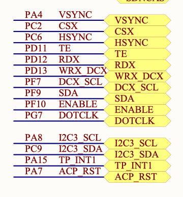
We can find that the LCD data and clock line are connected to SPI5 of STM32F429 as following:
- PF7 as SPI5 SCK.
- PF9 as SPI5 MOSI.
Also,
- PC2 as Chip select.
- PD13 as Data Command selection.
For the touch interface, we can see that it is connected to I2C3 bus with the following pins:
- PA8 as SCL.
- PC9 as SDA.
After obtaining all the required pins, we shall develop the following drivers:
- SPI to transmit data to the LCD using DMA.
- I2C to get the touch values.
Before starting developing the drive, please take a look at the following guides:
We start off by creatine new source and header file with name of LCD_Pins.c and LCD_Pins.h respectively.
Within the header file:
#ifndef LCD_PINS_H_
#define LCD_PINS_H_

#include "delay.h"
#include "stm32f4xx.h"

#define LCD_RES_HIGH(void)			GPIOA->BSRR=GPIO_BSRR_BS7
#define LCD_RES_LOW(void)			GPIOA->BSRR=GPIO_BSRR_BR7

#define LCD_CS_HIGH(void)			GPIOC->BSRR=GPIO_BSRR_BS2
#define LCD_CS_LOW(void)			GPIOC->BSRR=GPIO_BSRR_BR2

#define LCD_DC_HIGH(void)			GPIOD->BSRR=GPIO_BSRR_BS13
#define LCD_DC_LOW(void)			GPIOD->BSRR=GPIO_BSRR_BR13


/*SPI */
void LCD_Pin_Init(void);
void LCD_SPI_Init(void);

/*LCD*/
void LCD_RST(void);
void LCD_Write_Cmd(uint8_t cmd);
void LCD_Write_Data (uint8_t data);
void spi5_transmit(uint8_t *data,uint32_t size);
void SPI5_Transmit_DMA(uint8_t *data,uint16_t size);

#endif /* LCD_PINS_H_ */
Within the source file:
#include "stm32f4xx.h"
#include "LCD_Pins.h"

#define AF05						0x05


void LCD_Pin_Init(void)
{
	RCC->AHB1ENR|=RCC_AHB1ENR_GPIOAEN|RCC_AHB1ENR_GPIOCEN|RCC_AHB1ENR_GPIODEN|RCC_AHB1ENR_GPIOFEN;

	/*PA7*/
	GPIOA->MODER|=GPIO_MODER_MODE7_0;
	GPIOA->MODER&=~GPIO_MODER_MODE7_1;
	GPIOA->OSPEEDR|=GPIO_OSPEEDR_OSPEED7;
	GPIOA->ODR|=GPIO_ODR_OD7;

	/*PC2*/
	GPIOC->MODER|=GPIO_MODER_MODE2_0;
	GPIOC->MODER&=~GPIO_MODER_MODE2_1;
	GPIOC->OSPEEDR|=GPIO_OSPEEDR_OSPEED2;
	GPIOC->ODR|=GPIO_ODR_OD2;


	/*PD13*/
	GPIOD->MODER|=GPIO_MODER_MODE13_0;
	GPIOD->MODER&=~GPIO_MODER_MODE13_1;
	GPIOD->OSPEEDR|=GPIO_OSPEEDR_OSPEED13;
	GPIOD->ODR|=GPIO_ODR_OD13;

	/*PF7 and PF9 for SPI5*/

	GPIOF->MODER|=GPIO_MODER_MODE7_1|GPIO_MODER_MODE9_1;
	GPIOF->MODER&=~(GPIO_MODER_MODE7_0|GPIO_MODER_MODE9_0);

	GPIOF->OSPEEDR|=GPIO_OSPEEDR_OSPEED7|GPIO_OSPEEDR_OSPEED9;

	GPIOF->AFR[0]|=(AF05<<GPIO_AFRL_AFSEL7_Pos);
	GPIOF->AFR[1]|=(AF05<<GPIO_AFRH_AFSEL9_Pos);


}


void LCD_SPI_Init(void)
{
	RCC->APB2ENR|=RCC_APB2ENR_SPI5EN;
	SPI5->CR1|=SPI_CR1_MSTR|SPI_CR1_SSM|SPI_CR1_SSI|SPI_CR1_BR_0;

	SPI5->CR2|=SPI_CR2_TXDMAEN;

	NVIC_EnableIRQ(SPI5_IRQn);


	RCC->AHB1ENR|=RCC_AHB1ENR_DMA2EN;

	DMA2_Stream4->CR&=~(DMA_SxCR_EN);

	while((DMA2_Stream4->CR &DMA_SxCR_EN)==DMA_SxCR_EN);

	DMA2_Stream4->CR|=(0x02<<DMA_SxCR_CHSEL_Pos)|(DMA_SxCR_MINC)|
			(DMA_SxCR_DIR_0)|(DMA_SxCR_TCIE);

	NVIC_EnableIRQ(DMA2_Stream4_IRQn);


	SPI5->CR1|=SPI_CR1_SPE;

}


void spi5_transmit(uint8_t *data,uint32_t size)
{
	uint32_t i=0;


	while(i<size)
	{
		/*Wait until TXE is set*/
		while(!(SPI5->SR & (SPI_SR_TXE))){}

		/*Write the data to the data register*/
		SPI5->DR = data[i];
		i++;
	}
	/*Wait until TXE is set*/
	while(!(SPI5->SR & (SPI_SR_TXE))){}

	/*Wait for BUSY flag to reset*/
	while((SPI5->SR & (SPI_SR_BSY))){}

	/*Clear OVR flag*/
	(void) SPI5->DR;
	(void) SPI5->SR;
}


void SPI5_Transmit_DMA(uint8_t *data,uint16_t size)
{
	DMA2_Stream4->M0AR= (uint32_t)data;
	DMA2_Stream4->NDTR=size;
	DMA2_Stream4->PAR=(uint32_t)&SPI5->DR;

	DMA2_Stream4->CR|=DMA_SxCR_EN;


}


void DMA2_Stream4_IRQHandler(void)
{
	if(DMA2->HISR&(DMA_HISR_TCIF4))
	{
		/*Enable SPI Tx buffer empty interrupt */

		SPI5->CR2|=SPI_CR2_TXEIE;

		/*Clear pending flag*/
		DMA2->HIFCR |=DMA_HIFCR_CTCIF4;
	}
}

__WEAK void SPI5_TX_Finished(void)
{
	/*Override with user code*/
}

void SPI5_IRQHandler(void)
{
	if ((SPI5->SR & SPI_SR_TXE) && ((SPI5->SR & SPI_SR_BSY)==0))
	{
		/*Set finished to 1*/
		SPI5_TX_Finished();

		/*Disable SPI Tx Buffer empty interrupt*/
		SPI5->CR2&=~SPI_CR2_TXEIE;


	}
}


void LCD_RST(void)
{
	LCD_RES_LOW();
	delay(50);
	LCD_RES_HIGH();
	delay(20);

}


void LCD_Write_Cmd(uint8_t cmd)
{
	LCD_CS_LOW();
	LCD_DC_LOW();
	spi5_transmit(&cmd,1);
	LCD_CS_HIGH();
}


void LCD_Write_Data (uint8_t data)
{
	LCD_CS_LOW();
	LCD_DC_HIGH();
	spi5_transmit (&data,1);
	LCD_CS_HIGH();
}
Create new source and header file with name of ILI9341.c and ILI9341.h respectively.
Within the header file:
#ifndef ILI9341_H_
#define ILI9341_H_

//List of includes
#include <stdbool.h>
#include "delay.h"
#include <stdint.h>
#include <math.h>


//LCD dimensions defines
#define ILI9341_WIDTH       				320
#define ILI9341_HEIGHT      				240


#define ILI9341_PIXEL_COUNT					ILI9341_WIDTH * ILI9341_HEIGHT


//ILI9341 LCD commands
#define ILI9341_RESET			 		    0x01
#define ILI9341_SLEEP_OUT		  			0x11
#define ILI9341_GAMMA			    		0x26
#define ILI9341_DISPLAY_OFF					0x28
#define ILI9341_DISPLAY_ON					0x29
#define ILI9341_COLUMN_ADDR					0x2A
#define ILI9341_PAGE_ADDR			  		0x2B
#define ILI9341_GRAM				    	0x2C
#define ILI9341_TEARING_OFF					0x34
#define ILI9341_TEARING_ON					0x35
#define ILI9341_DISPLAY_INVERSION			0xb4
#define ILI9341_MAC			        		0x36
#define ILI9341_PIXEL_FORMAT    			0x3A
#define ILI9341_WDB			    	  		0x51
#define ILI9341_WCD				      		0x53
#define ILI9341_RGB_INTERFACE   			0xB0
#define ILI9341_FRC					    	0xB1
#define ILI9341_BPC					    	0xB5
#define ILI9341_DFC				 	    	0xB6
#define ILI9341_Entry_Mode_Set				0xB7
#define ILI9341_POWER1						0xC0
#define ILI9341_POWER2						0xC1
#define ILI9341_VCOM1						0xC5
#define ILI9341_VCOM2						0xC7
#define ILI9341_POWERA						0xCB
#define ILI9341_POWERB						0xCF
#define ILI9341_PGAMMA						0xE0
#define ILI9341_NGAMMA						0xE1
#define ILI9341_DTCA						0xE8
#define ILI9341_DTCB						0xEA
#define ILI9341_POWER_SEQ					0xED
#define ILI9341_3GAMMA_EN					0xF2
#define ILI9341_INTERFACE					0xF6
#define ILI9341_PRC				   	  		0xF7
#define ILI9341_VERTICAL_SCROLL 			0x33

#define ILI9341_MEMCONTROL         			0x36
#define ILI9341_MADCTL_MY  					0x80
#define ILI9341_MADCTL_MX  					0x40
#define ILI9341_MADCTL_MV  					0x20
#define ILI9341_MADCTL_ML  					0x10
#define ILI9341_MADCTL_RGB 					0x00
#define ILI9341_MADCTL_BGR 					0x08
#define ILI9341_MADCTL_MH  					0x04


//4. Initialise function
void ILI9341_Init();

void setAddrWindow(uint16_t X1, uint16_t Y1, uint16_t X2, uint16_t Y2);

void ILI9341_DrawBitmap(uint16_t w, uint16_t h, uint8_t *s);

void ILI9341_setRotation(uint8_t rotate);

#endif
Within the source file:
//most of the functions has been documented in the interface file (ILI9341.h)
#include "ILI9341.h"
#include "LCD_Pins.h"
#include "stdlib.h"

static uint8_t rotationNum=1;


//initialize the tft
void ILI9341_Init(void)
{


	LCD_Write_Cmd (ILI9341_DISPLAY_OFF); // display off
	//------------power control------------------------------
	LCD_Write_Cmd (ILI9341_POWER1); // power control
	LCD_Write_Data   (0x26); // GVDD = 4.75v
	LCD_Write_Cmd (ILI9341_POWER2); // power control
	LCD_Write_Data   (0x11); // AVDD=VCIx2, VGH=VCIx7, VGL=-VCIx3
	//--------------VCOM-------------------------------------
	LCD_Write_Cmd (ILI9341_VCOM1); // vcom control
	LCD_Write_Data   (0x35); // Set the VCOMH voltage (0x35 = 4.025v)
	LCD_Write_Data   (0x3e); // Set the VCOML voltage (0x3E = -0.950v)
	LCD_Write_Cmd (ILI9341_VCOM2); // vcom control
	LCD_Write_Data   (0xbe);

	//------------memory access control------------------------
	LCD_Write_Cmd (ILI9341_MAC); // memory access control
	LCD_Write_Data(0x48);

	LCD_Write_Cmd (ILI9341_PIXEL_FORMAT); // pixel format set
	LCD_Write_Data   (0x55); // 16bit /pixel

	LCD_Write_Cmd(ILI9341_FRC);
	LCD_Write_Data(0);
	LCD_Write_Data(0x1F);
	//-------------ddram ----------------------------
	LCD_Write_Cmd (ILI9341_COLUMN_ADDR); // column set
	LCD_Write_Data   (0x00); // x0_HIGH---0
	LCD_Write_Data   (0x00); // x0_LOW----0
	LCD_Write_Data   (0x00); // x1_HIGH---240
	LCD_Write_Data   (0x1D); // x1_LOW----240
	LCD_Write_Cmd (ILI9341_PAGE_ADDR); // page address set
	LCD_Write_Data   (0x00); // y0_HIGH---0
	LCD_Write_Data   (0x00); // y0_LOW----0
	LCD_Write_Data   (0x00); // y1_HIGH---320
	LCD_Write_Data   (0x27); // y1_LOW----320

	LCD_Write_Cmd (ILI9341_TEARING_OFF); // tearing effect off
	//LCD_write_cmd(ILI9341_TEARING_ON); // tearing effect on
	//LCD_write_cmd(ILI9341_DISPLAY_INVERSION); // display inversion
	LCD_Write_Cmd (ILI9341_Entry_Mode_Set); // entry mode set
	// Deep Standby Mode: OFF
	// Set the output level of gate driver G1-G320: Normal display
	// Low voltage detection: Disable
	LCD_Write_Data   (0x07);
	//-----------------display------------------------
	LCD_Write_Cmd (ILI9341_DFC); // display function control
	//Set the scan mode in non-display area
	//Determine source/VCOM output in a non-display area in the partial display mode
	LCD_Write_Data   (0x0a);
	//Select whether the liquid crystal type is normally white type or normally black type
	//Sets the direction of scan by the gate driver in the range determined by SCN and NL
	//Select the shift direction of outputs from the source driver
	//Sets the gate driver pin arrangement in combination with the GS bit to select the optimal scan mode for the module
	//Specify the scan cycle interval of gate driver in non-display area when PTG to select interval scan
	LCD_Write_Data   (0x82);
	// Sets the number of lines to drive the LCD at an interval of 8 lines
	LCD_Write_Data   (0x27);
	LCD_Write_Data   (0x00); // clock divisor

	LCD_Write_Cmd (ILI9341_SLEEP_OUT); // sleep out
	delay(100);
	LCD_Write_Cmd (ILI9341_DISPLAY_ON); // display on
	delay(100);
	LCD_Write_Cmd (ILI9341_GRAM); // memory write
	delay(5);

}

//set the address of the pixel in the memory
void setAddrWindow(uint16_t X1, uint16_t Y1, uint16_t X2, uint16_t Y2)
{

	LCD_Write_Cmd(0x2A); // Column addr set
	LCD_Write_Data(X1>>8);
	LCD_Write_Data(X1);     // XSTART
	LCD_Write_Data(X2>>8);
	LCD_Write_Data(X2);     // XEND

	LCD_Write_Cmd(0x2B); // Row addr set
	LCD_Write_Data(Y1>>8);
	LCD_Write_Data(Y1);     // YSTART
	LCD_Write_Data(Y2>>8);
	LCD_Write_Data(Y2);     // YEND

	LCD_Write_Cmd(0x2C); // write to RAM
}


void ILI9341_setRotation(uint8_t rotate)
{
	switch(rotate)
	{
	case 1:
	rotationNum = 1;
	LCD_Write_Cmd(ILI9341_MEMCONTROL);
	LCD_Write_Data(ILI9341_MADCTL_MY | ILI9341_MADCTL_BGR);
	break;
	case 2:
	rotationNum = 2;
	LCD_Write_Cmd(ILI9341_MEMCONTROL);
	LCD_Write_Data(ILI9341_MADCTL_MV | ILI9341_MADCTL_BGR);
	break;
	case 3:
	rotationNum = 3;
	LCD_Write_Cmd(ILI9341_MEMCONTROL);
	LCD_Write_Data(ILI9341_MADCTL_MX | ILI9341_MADCTL_BGR);
	break;
	case 4:
	rotationNum = 4;
	LCD_Write_Cmd(ILI9341_MEMCONTROL);
	LCD_Write_Data(ILI9341_MADCTL_MX | ILI9341_MADCTL_MY | ILI9341_MADCTL_MV | ILI9341_MADCTL_BGR);
	break;
	default:
	rotationNum = 1;
	LCD_Write_Cmd(ILI9341_MEMCONTROL);
	LCD_Write_Data(ILI9341_MADCTL_MY | ILI9341_MADCTL_BGR);
	break;
	}
}


static void ConvHL(uint8_t *s, int32_t l)
{
	uint8_t v;
	while (l > 0) {
		v = *(s+1);
		*(s+1) = *s;
		*s = v;
		s += 2;
		l -= 2;
	}
}


void ILI9341_DrawBitmap(uint16_t w, uint16_t h, uint8_t *s)
{
	LCD_Write_Cmd(0x2c);
	LCD_DC_HIGH();
	LCD_CS_LOW();
	ConvHL(s, (int32_t)w*h*2);
	SPI5_Transmit_DMA((uint8_t*)s, w*h*2);

}
Now, the LCD is ready for LvGL integration.
2. Touch Initialization:
Since the touch driver is connected to I2C3, we shall initialize the bus first.
Create new source and header file with name i2c3.c and i2c.h respectively.
Within the header file:
#ifndef I2C3_H_
#define I2C3_H_

#include "stdint.h"

void i2c3_init(void);
void I2C3_WriteByte(uint8_t saddr,uint8_t maddr, uint8_t data);
void I2C3_ReadMultiByte(uint8_t saddr,uint8_t maddr, uint8_t* data, uint16_t n);
void i2c3_WriteMulti(uint8_t saddr,uint8_t maddr,uint8_t *buffer, uint8_t length);
void i2c3_readByte(uint8_t saddr,uint8_t maddr, uint8_t *data);
void i2c3_bus_scan(void);

#endif /* I2C3_H_ */
Within the source file file:
#include "STM32F4xx.h"

#include "i2c3.h"
#include "stdio.h"

#define AF04 0x04

void i2c3_init(void)
{
	/*GPIO Configuration*/

	/*Enable Clock access to GPIOA and GPIOC*/
	RCC->AHB1ENR|=RCC_AHB1ENR_GPIOAEN|RCC_AHB1ENR_GPIOCEN;

	/*GPIOA configuration*/
	GPIOA->MODER|=GPIO_MODER_MODE8_1;
	GPIOA->MODER&=~GPIO_MODER_MODE8_0;

	GPIOA->OTYPER|=GPIO_OTYPER_OT8;

	GPIOA->AFR[1]|=(AF04<<GPIO_AFRH_AFSEL8_Pos);

	/*GPIOC configuration*/
	GPIOC->MODER|=GPIO_MODER_MODE9_1;
	GPIOC->MODER&=~GPIO_MODER_MODE9_0;

	GPIOC->OTYPER|=GPIO_OTYPER_OT9;

	GPIOC->AFR[1]|=(AF04<<GPIO_AFRH_AFSEL9_Pos);


	/*I2C3 Init*/

	RCC->APB1ENR|=RCC_APB1ENR_I2C3EN;

	I2C3->CR1=I2C_CR1_SWRST;//reset i2c
	I2C3->CR1&=~I2C_CR1_SWRST;// release reset i2c
	I2C3->CR2|=0x2d;//set clock source to 42MHz
	I2C3->CCR=0xe1 ;  //based on calculation
	I2C3->TRISE=0x2e; //output max rise
	I2C3->CR1|=I2C_CR1_PE; //enable I2C

}

void I2C3_WriteByte(uint8_t saddr,uint8_t maddr, uint8_t data)
{
	while(I2C3->SR2&I2C_SR2_BUSY){;}          /*wait until bus not busy*/
	I2C3->CR1|=I2C_CR1_START;                 /*generate start*/
	while(!(I2C3->SR1&I2C_SR1_SB)){;}         /*wait until start bit is set*/
	I2C3->DR = saddr<< 1;                 	 /* Send slave address*/
	while(!(I2C3->SR1&I2C_SR1_ADDR)){;}      /*wait until address flag is set*/
	(void)I2C3->SR2; 							/*clear SR2 by reading it */
	while(!(I2C3->SR1&I2C_SR1_TXE)){;}       /*Wait until Data register empty*/
	I2C3->DR = maddr;                        /* send memory address*/
	while(!(I2C3->SR1&I2C_SR1_TXE)){;}       /*wait until data register empty*/
	I2C3->DR = data;
	while (!(I2C3->SR1 & I2C_SR1_BTF));      /*wait until transfer finished*/
	I2C3->CR1 |=I2C_CR1_STOP;
}

void I2C3_ReadMultiByte(uint8_t saddr,uint8_t maddr, uint8_t* data, uint16_t n)
{
	while (I2C3->SR2 & I2C_SR2_BUSY){;}
	I2C3->CR1|=I2C_CR1_START;
	while(!(I2C3->SR1 & I2C_SR1_SB)){;}
	I2C3->DR=saddr<<1;
	while(!(I2C3->SR1 & I2C_SR1_ADDR)){;}
	(void)I2C3->SR2;
	while(!(I2C3->SR1&I2C_SR1_TXE)){;}
	I2C3->DR = maddr;
	while(!(I2C3->SR1&I2C_SR1_TXE)){;}
	I2C3->CR1|=I2C_CR1_START;
	while(!(I2C3->SR1 & I2C_SR1_SB)){;}
	I2C3->DR=saddr<<1|1;
	while(!(I2C3->SR1 & I2C_SR1_ADDR)){;}
	(void)I2C3->SR2;
	I2C3->CR1|=I2C_CR1_ACK;
	while(n>0U)
	{
		if(n==1U)
		{
			I2C3->CR1&=~I2C_CR1_ACK;
			I2C3->CR1|=I2C_CR1_STOP;
			while(!(I2C3->SR1&I2C_SR1_RXNE)){;}
			*data++=I2C3->DR;
			break;
		}
		else
		{
			while(!(I2C3->SR1&I2C_SR1_RXNE)){;}
			(*data++)=I2C3->DR;
			n--;

		}
	}
}


void i2c3_WriteMulti(uint8_t saddr,uint8_t maddr,uint8_t *buffer, uint8_t length)
{
	while (I2C3->SR2 & I2C_SR2_BUSY);           //wait until bus not busy
	I2C3->CR1 |= I2C_CR1_START;                 //generate start
	while (!(I2C3->SR1 & I2C_SR1_SB)){;}		//wait until start is generated

	I2C3->DR = saddr<< 1;                 	 	// Send slave address
	while (!(I2C3->SR1 & I2C_SR1_ADDR)){;}      //wait until address flag is set
	(void)I2C3->SR2; 						    //Clear SR2
	while (!(I2C3->SR1 & I2C_SR1_TXE));         //Wait until Data register empty
	I2C3->DR = maddr;                      		// send memory address
	while (!(I2C3->SR1 & I2C_SR1_TXE));         //wait until data register empty
	//sending the data
	for (uint8_t i=0;i<length;i++)
	 {
		I2C3->DR=buffer[i]; 					//filling buffer with command or data
		while (!(I2C3->SR1 & I2C_SR1_BTF));
	 }

	I2C3->CR1 |= I2C_CR1_STOP;					//wait until transfer finished

}


void i2c3_readByte(uint8_t saddr,uint8_t maddr, uint8_t *data)
{

	while(I2C3->SR2&I2C_SR2_BUSY){;}
	I2C3->CR1|=I2C_CR1_START;
	while(!(I2C3->SR1&I2C_SR1_SB)){;}
	I2C3->DR=saddr<<1;
	while(!(I2C3->SR1&I2C_SR1_ADDR)){;}
	(void)I2C3->SR2;
	while(!(I2C3->SR1&I2C_SR1_TXE)){;}
	I2C3->DR=maddr;
	while(!(I2C3->SR1&I2C_SR1_TXE)){;}
	I2C3->CR1|=I2C_CR1_START;
	while(!(I2C3->SR1&I2C_SR1_SB)){;}
	I2C3->DR=saddr<<1|1;
	while(!(I2C3->SR1&I2C_SR1_ADDR)){;}
	I2C3->CR1&=~I2C_CR1_ACK;
	(void)I2C3->SR2;
	I2C3->CR1|=I2C_CR1_STOP;
	while(!(I2C3->SR1&I2C_SR1_RXNE)){;}
	*data=I2C3->DR;

}
Now, the I2C3 is ready to communicate with i2c slave devices.
For the touch controller, create new source and header file with name of STMPE811.c and STMPE811.h respectively.
Within the header file:
#ifndef STMPE811_H_
#define STMPE811_H_

#include "stdint.h"

#define deviceAddress 0x41


typedef enum TouchDetect
{
	touched =1,
	no_touch=0

}TouchDetect_t;


#define STMPE811_REG_SYS_CTRL2 			0x04 /*Clock control*/
#define STMPE811_REG_SYS_CTRL1 			0x03 /*Reset control*/
#define STMPE811_REG_IO_AF              0x17 /*Alternate function register*/
#define STMPE811_REG_ADC_CTRL1          0x20 /*ADC control*/
#define STMPE811_REG_ADC_CTRL2          0x21 /*ADC control*/
#define STMPE811_REG_TSC_CFG            0x41 /*Touch Configuration*/
#define STMPE811_REG_FIFO_TH            0x4A /*FIFO threshold*/
#define STMPE811_REG_FIFO_STA           0x4B /*FIFO status*/
#define STMPE811_REG_TSC_FRACT_XYZ      0x56 /*Touchscreen controller FRACTION_Z*/
#define STMPE811_REG_TSC_I_DRIVE        0x58 /*Touchscreen controller drive*/
#define STMPE811_REG_TSC_CTRL           0x40 /*touchscreen controller control register*/
#define STMPE811_REG_INT_CTRL			0x09 /*Interrupt control register*/
#define STMPE811_REG_INT_EN				0x0A /*Interrupt enable register*/
#define STMPE811_REG_INT_STA            0x0B /*Interrupt status register*/
#define STMPE811_REG_TSC_DATA_INC       0x57 /*Touchscreen controller DATA Incremental*/
#define STMPE811_REG_TSC_DATA_NON_INC   0xD7 /*Touchscreen controller DATA Non-Incremental*/
#define STMPE811_REG_FIFO_SIZE          0x4C /*FIFO size*/

/*IO expander facilities*/
#define STMPE811_ADC_FCT                0x01
#define STMPE811_TS_FCT                 0x02
#define STMPE811_IO_FCT                 0x04
#define STMPE811_TEMPSENS_FCT           0x08


/* Touch Screen Pins definition */
#define STMPE811_TOUCH_YD               STMPE811_PIN_7
#define STMPE811_TOUCH_XD               STMPE811_PIN_6
#define STMPE811_TOUCH_YU               STMPE811_PIN_5
#define STMPE811_TOUCH_XU               STMPE811_PIN_4
#define STMPE811_TOUCH_IO_ALL           0x00

/* IO Pins definition */
#define STMPE811_PIN_0                  0x01
#define STMPE811_PIN_1                  0x02
#define STMPE811_PIN_2                  0x04
#define STMPE811_PIN_3                  0x08
#define STMPE811_PIN_4                  0x10
#define STMPE811_PIN_5                  0x20
#define STMPE811_PIN_6                  0x40
#define STMPE811_PIN_7                  0x80
#define STMPE811_PIN_ALL                0xFF

#define STMPE811_TS_CTRL_ENABLE         0x01
#define STMPE811_TS_CTRL_STATUS         0x80


#define Touch_XMIN 						390
#define Touch_YMIN 						359
#define Touch_XMAX 						3830
#define Touch_YMAX 						3895
#define Touch_WIDTH 					(Touch_XMAX - Touch_XMIN)
#define Touch_HEIGHT 					(Touch_YMAX - Touch_YMIN)


void STMPE811_Touch_Enable(void);
TouchDetect_t isToched(void);
void getTouchValue(uint16_t *X, uint16_t *Y);
uint16_t getID(void);


#endif /* STMPE811_H_ */
Within the source file:
#include "i2c3.h"
#include "STMPE811.h"
#include "delay.h"
#include "STM32F4xx.h"


void STMPE811_Touch_Enable(void)
{

	uint8_t mode;

	/* Power Down the stmpe811 */
	I2C3_WriteByte(deviceAddress, STMPE811_REG_SYS_CTRL1, 2);

	/* Wait for a delay to ensure registers erasing */
	delay(10);

	/* Power On the Codec after the power off => all registers are reinitialized */
	I2C3_WriteByte(deviceAddress, STMPE811_REG_SYS_CTRL1, 0);

	/* Wait for a delay to ensure registers erasing */
	delay(2);

	/*Disable clock access to GPIO*/

	i2c3_readByte(deviceAddress, STMPE811_REG_SYS_CTRL2, &mode);

	mode &= ~(STMPE811_IO_FCT);

	/* Write the new register value */
	I2C3_WriteByte(deviceAddress, STMPE811_REG_SYS_CTRL2, mode);


	/*Select TSC pins in TSC alternate mode */

	I2C3_WriteByte(deviceAddress, STMPE811_REG_IO_AF, STMPE811_TOUCH_IO_ALL);


	mode&= ~(STMPE811_TS_FCT | STMPE811_ADC_FCT);

	/* Write the new register value */
	I2C3_WriteByte(deviceAddress, STMPE811_REG_SYS_CTRL2, mode);


	/* Select Sample Time, bit number and ADC Reference */
	I2C3_WriteByte(deviceAddress, STMPE811_REG_ADC_CTRL1, 0x49);

	/* Wait for 2 ms */
	delay(2);

	/* Select the ADC clock speed: 3.25 MHz */
	I2C3_WriteByte(deviceAddress, STMPE811_REG_ADC_CTRL2, 0x01);


	/* Select 2 nF filter capacitor */
	/* Configuration:
	- Touch average control    : 8 samples
	- Touch delay time         : 500 uS
	- Panel driver setting time: 500 uS
	*/
	I2C3_WriteByte(deviceAddress, STMPE811_REG_TSC_CFG, 0xDA);

	/* Configure the Touch FIFO threshold: single point reading */
	I2C3_WriteByte(deviceAddress, STMPE811_REG_FIFO_TH, 0x01);

	/* Clear the FIFO memory content. */
	I2C3_WriteByte(deviceAddress, STMPE811_REG_FIFO_STA, 0x01);

	/* Put the FIFO back into operation mode  */
	I2C3_WriteByte(deviceAddress, STMPE811_REG_FIFO_STA, 0x00);

	/* Set the range and accuracy pf the pressure measurement (Z) :
	- Fractional part :7a
	- Whole part      :1
	*/
	I2C3_WriteByte(deviceAddress, STMPE811_REG_TSC_FRACT_XYZ, 0x07);

	/* Set the driving capability (limit) of the device for TSC pins: 50mA */
	I2C3_WriteByte(deviceAddress, STMPE811_REG_TSC_I_DRIVE, 0x01);

	/* Touch screen control configuration (enable TSC):
	- No window tracking index
	- XYZ acquisition mode
	*/
	I2C3_WriteByte(deviceAddress, STMPE811_REG_TSC_CTRL, 0x01);

	/*  Clear all the status pending bits if any */
	I2C3_WriteByte(deviceAddress, STMPE811_REG_INT_STA, 0xFF);


	/*Delay for 5ms*/

	delay(5);

}


TouchDetect_t isToched(void)
{

	uint8_t state=0;
	uint8_t value=0;

	i2c3_readByte(deviceAddress, STMPE811_REG_TSC_CTRL, &value);

	value&=STMPE811_TS_CTRL_STATUS;

	state=(value&STMPE811_TS_CTRL_STATUS)==0x80;

	if(value==STMPE811_TS_CTRL_STATUS)
	{
		i2c3_readByte(deviceAddress,STMPE811_REG_FIFO_SIZE, &value);
		if(value>0)
		{
			return touched;
		}
	}

	else
	{
		/* Clear the FIFO memory content. */
		I2C3_WriteByte(deviceAddress, STMPE811_REG_FIFO_STA, 0x01);

		/* Put the FIFO back into operation mode  */
		I2C3_WriteByte(deviceAddress, STMPE811_REG_FIFO_STA, 0x00);
	}


	return no_touch;
}


void getTouchValue(uint16_t *X, uint16_t *Y)
{
	uint32_t uldataXYZ;
	uint8_t  dataXYZ[4];
	uint8_t mode;
	uint16_t localx=0,localy =0;


		I2C3_ReadMultiByte(deviceAddress, STMPE811_REG_TSC_DATA_NON_INC, dataXYZ, 4) ;

		/* Calculate positions values */
		uldataXYZ = (dataXYZ[0] << 24)|(dataXYZ[1] << 16)|(dataXYZ[2] << 8)|(dataXYZ[3] << 0);
		*X=(uldataXYZ >> 20) & 0x00000FFF;
		*Y= (uldataXYZ >>  8) & 0x00000FFF;

		/* Reset FIFO */
		mode=0x01;
		I2C3_WriteByte(deviceAddress, STMPE811_REG_FIFO_STA, mode);

		/* Enable the FIFO again */
		mode=0x00;
		I2C3_WriteByte(deviceAddress, STMPE811_REG_FIFO_STA, mode);


}


uint16_t getID(void)
{
	uint8_t data[2];
	I2C3_ReadMultiByte(deviceAddress, 0x00, data, 2);
	uint16_t data_re=data[0]<<8|data[1];
	return (data_re);

}
Now, the touch is ready to read the touches on the screen.
In part 3, we shall integrate LvGL v9 and start displaying demo.
Stay tuned.
Add Comment