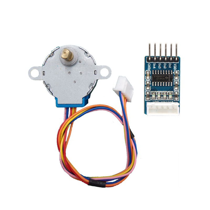
In this guide,, we will learn to interface a stepper motor with STM32F411RE Nucleo-64. There are many options available for stepper motors. But in this tutorial, we will use an inexpensive 28BYJ-48 stepper motor for interfacing with STM32F411. Because it comes with a UL2003 driver. Moreover, it is a low-cost solution to learn about stepper motors control and working. But the concepts learned with this type can be easily applied to other high torque industrial stepper motors also.
In this guide, we will cover the following:
- 28BYJ-48 Stepper Motor
- Connection diagram
- Code
- Demo
1.1 28BYJ-48 Stepper Motor pin configuration:
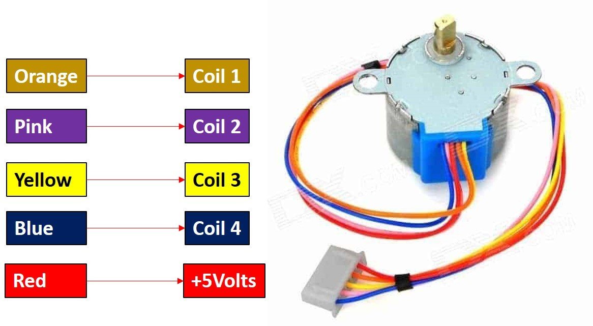
The following figure shows the pinout diagram of 28BYJ-48 stepper motor. It consists of 5 pins. Out of these 5 pins, four pins are used to provide sequence logic to the coils and one pin is +5 volts supply pin.
1.2 Pin Configuration Details
| Pin | Name | Color | Functionality |
| 1 | Coil 1 | Orange | These are coils used to control the step sequence of the stepper motor. One end of each coil is connected with +5V and the other end will be connected with ULN2003 driver output. |
| 2 | Coil 2 | Pink | |
| 3 | 5V | Red | Used to apply +5 volt supply to the stepper motor. This voltage appears across the coils when a specific coil is ground through a control sequence. |
| 4 | Coil 3 | Yellow | |
| 5 | Coil 4 | Blue |
The specifications of the S8BYJ-48 stepper motor are:
- It is a unipolar 5 pin coil with a rated DC voltage of 5V.
- It has 4 phases with a stride angle of 5.625°/64.
- The frequency of this stepper motor is 100Hz and insulated power is 600VAC/1mA/1s.
- The half-step method is recommended for driving this stepper motor.
- The value of pull in torque for a stepper motor is 300 gf.cm.
1.3 ULN2003 Stepper Motor Driver Module
Now the first question which comes to your mind is why do we need a ULN2003 driver to drive stepper motors? This is because the current consumption of 28BYJ-48 is around 240mA. That means the current required to drive coils by applying a sequence of control signals is also almost 200mA. GPIO pins of STM32F411 can not provide current of this magnitude. Therefore, we need a ULN2003 driver which translates low current output of TM4C123 GPIO pins into higher current that meets the requirement of stepper motor control signals.
Stepper Motor Driver Module Pinout
ULN2003 driver IC consists of 7 darlington pair transistor outputs. Each output can drive 500mA and 50V load. The input to each 7 darlington pair transistor can be a signal from the microcontroller such as STM32F411 microcontroller. To drive a stepper motor, this driver board used only four outputs. The following diagram shows the ULN2003 motor driver board and details of their components:

2.1 Connection:
So far, we learnt about the stepper motor and it’s driver. Let’s continue with the actual connection to STM32F411 and how to code
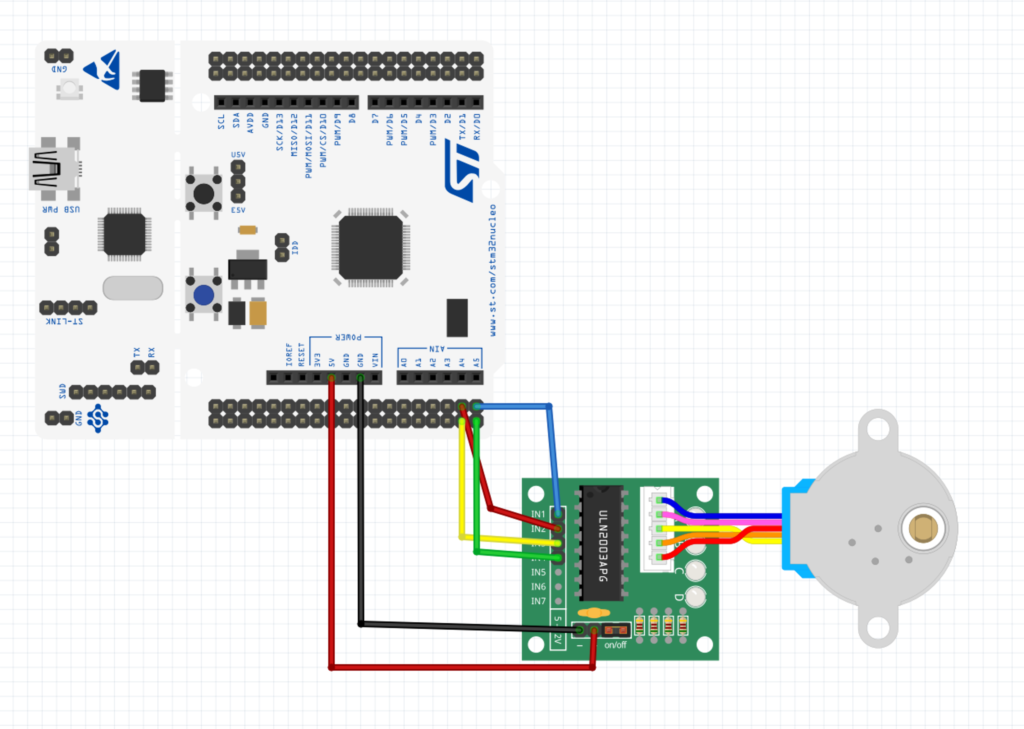
PC0->IN1
PC1->IN2
PC2->IN3
PC4->IN4
2.2 Driving Modes
Full Drive Sequence Mode
In this mode, two coils are energized at a time that means two windings of stepper motor energized together. Therefore, motor runs at full torque. We apply this sequence to input pins of the stepper motor through a UNL2003 driver.
| Step | Blue | Pink | Yellow | Orange |
|---|---|---|---|---|
| 1 | 1 | 1 | 0 | 0 |
| 2 | 0 | 1 | 1 | 0 |
| 3 | 0 | 0 | 1 | 1 |
| 4 | 1 | 0 | 0 | 1 |
Half Drive Sequence Mode
In this mode, we control the phases or coils with alternate one and two phase control as shown in the table below. But, in this mode, motor runs at low torque.
| Step | Blue | Pink | Yellow | Orange |
|---|---|---|---|---|
| 1 | 1 | 0 | 0 | 0 |
| 2 | 1 | 1 | 0 | 0 |
| 3 | 0 | 1 | 0 | 0 |
| 4 | 0 | 1 | 1 | 0 |
| 5 | 0 | 0 | 1 | 1 |
| 6 | 0 | 0 | 0 | 1 |
| 7 | 1 | 0 | 0 | 1 |
| 8 | 1 | 0 | 0 | 0 |
Wave Drive Mode
Like full-drive mode, only one coil is turned on at a time but with a drive sequence as shown below. The only advantage of this method is that a stepper motor consumes less power.
| Step | Blue | Pink | Yellow | Orange |
|---|---|---|---|---|
| 1 | 1 | 0 | 0 | 0 |
| 2 | 0 | 1 | 0 | 0 |
| 3 | 0 | 0 | 1 | 0 |
| 4 | 0 | 0 | 0 | 1 |
We shall use Full drive sequence mode
3. Code:
#include "stm32f4xx.h"                  // Device header
//delay in millisecond
void Delay_ms(int delay)

{

int i;

for(; delay>0 ;delay--)

{

for(i =0; i<3195;i++);

}

}


int main(void)
	{
	//Enable clock access to GPIOC
	RCC->AHB1ENR|=RCC_AHB1ENR_GPIOCEN;
	//Set PC0, PC1, PC2 and PC3 to output
	GPIOC->MODER|=GPIO_MODER_MODE0_0|GPIO_MODER_MODE1_0|GPIO_MODER_MODE2_0|GPIO_MODER_MODE3_0;

	while(1)
		{
		for(int i=0; i<500; i++) // take 500 steps to complete one revolution
		{
		//apply full drive clockwise rotation sequence
	  GPIOC->ODR = 0x08;
    Delay_ms(4);
    GPIOC->ODR = 0x04;
    Delay_ms(4);
    GPIOC->ODR = 0x02;
    Delay_ms(4);
    GPIOC->ODR = 0x01;
    Delay_ms(4);
}
Delay_ms(1000);
for(int i=0; i<100; i++) // rotate 100 steps counter clockwise
		{

	  GPIOC->ODR = 0x01;
    Delay_ms(4);
    GPIOC->ODR = 0x02;
    Delay_ms(4);
    GPIOC->ODR = 0x04;
    Delay_ms(4);
    GPIOC->ODR = 0x08;
    Delay_ms(4);
}

		Delay_ms(1000);
		}

	}
4. Demo
Note: My stepper motor sometimes gets stuck for some reason.
Happy Coding 😀
9 Comments
try adding an external 5volt to the stepper driver , might solve your getting stuck problem..
I figured out the issue, it is so old (7 years old) and left in dust for almost 5 years.
I tried with brand new motor, no issue.
No need to external power since the motor is not loaded
well done!
This experiment do with stm32H7 series.tell me sir
Hi,
I don’t have H7. However, I took a look at the register set and it is easy easy to port my code from F4 to H7
follow the same steps and you should be ok
where write code
Check out section 3.
Thanks for all sharing and advice,which helps me learn a lot ,this topic article is so useful.
You are welcome.
Add Comment