In this guide, we shall see how to configure the ADC to be triggered by a timer and acquire the ADC periodically.
In this guide, we shall cover the following:
- ADC trigger sources in STM32.
- Driver Development.
- Results.
1. ADC Trigger sources in STM32:
In STM32 microcontrollers, a timer-triggered ADCallows for automatic ADC conversions based on timer events. Instead of manually initiating ADC conversions using software triggers, you can configure the ADC to start conversions periodically using a timer as the trigger source. Let’s delve into the details:
- Timer Trigger Sources:
- The timer’s trigger output (TRGO) event can be configured to initiate ADC conversions. This feature is particularly useful for achieving a desired ADC sampling rate with minimal CPU intervention.
- You can set the ADC to start conversions at specific intervals (e.g., every 20 ms) by configuring the timer trigger.
- Applications include LED dimming, where you read an analog input (e.g., from a potentiometer) and control LED brightness using PWM output.
- External Trigger Sources:
- The ADC can also be triggered by external signals (e.g., GPIO pins) using the EXTI_x pins.
- This feature is handy for synchronizing multiple ADCs across different microcontrollers to start conversions simultaneously.
- It’s essential for advanced measurement systems that require precise timing relative to other signals.
2. Driver Development:
We start off by creating new project with name of ADC_DMA.
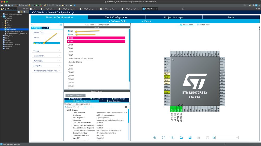
From pinout and configuration, select analog and select ADC. After that, enable IN0 and IN1 as following:
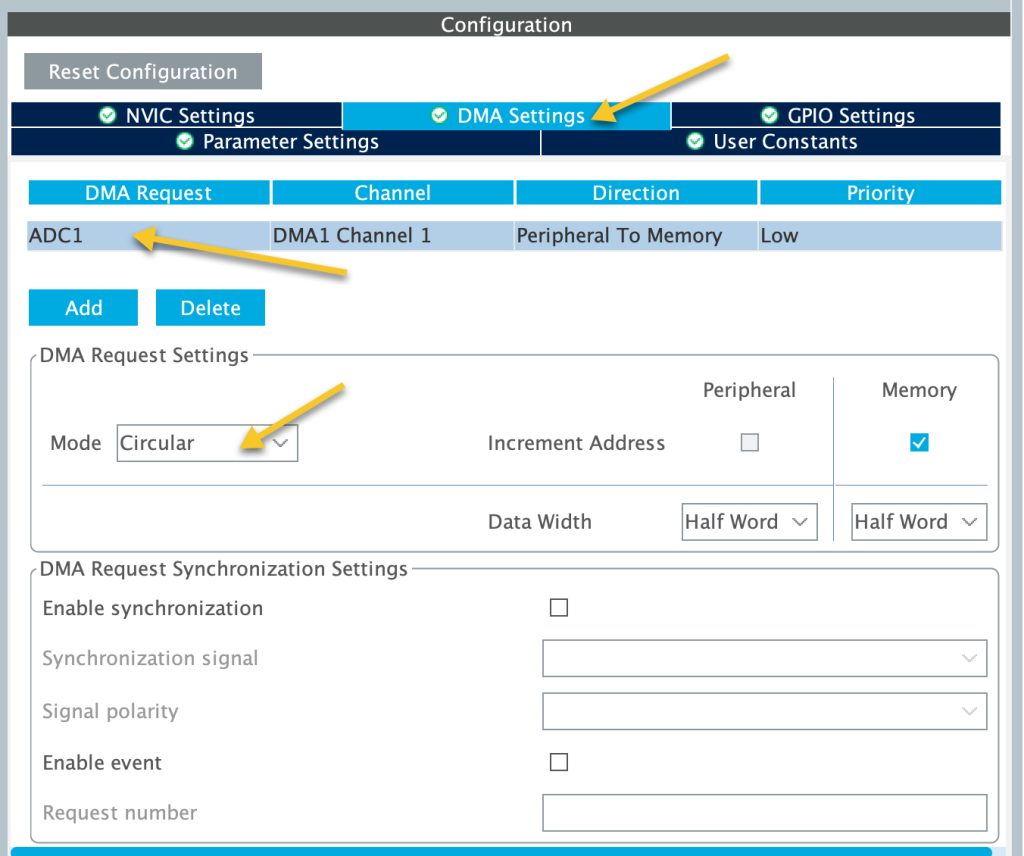
From DMA tab, enable the DMA for the ADC and set the mode to circular mode as following:
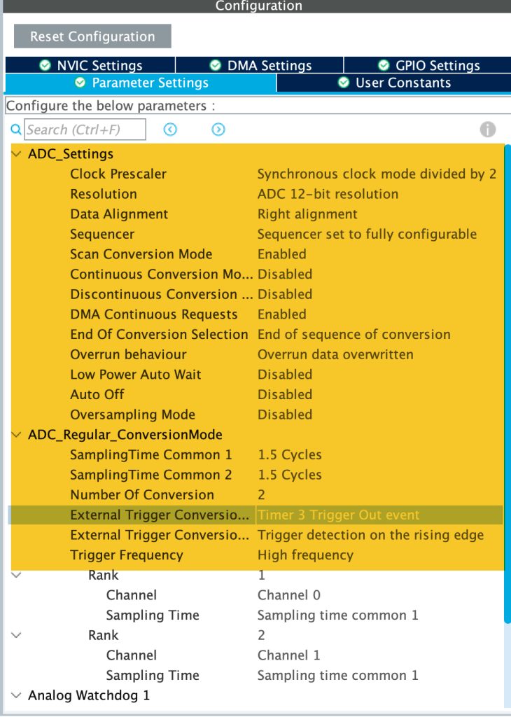
Set the ADC parameter as following:
- First set number of conversion to 2.
- Disable continuous conversion mode.
- Enable DMA continuous request.
- In Rank 1, set the channel to be channel0.
- In Rank 2. set the channel to be channel1.
- Set External Trigger Conversion to be Timer 3 Trigger Out Event.
- Set the edge of the trigger to be rising edge.
- Set the frequency to be high frequency.
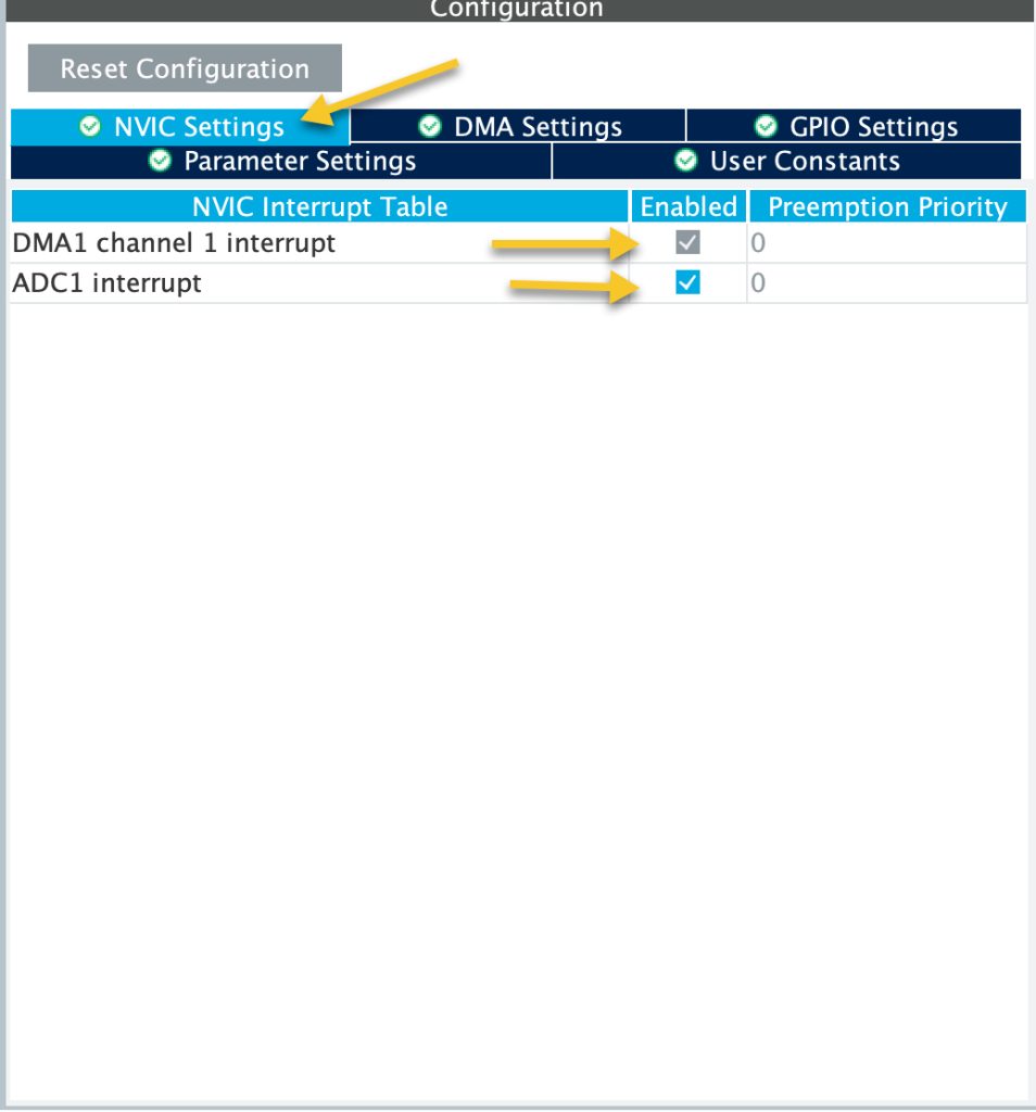
From the NVIC of the ADC, make sure to enable the interrupt of the ADC as following:
Now, from timers section, enable the timer3 as following:
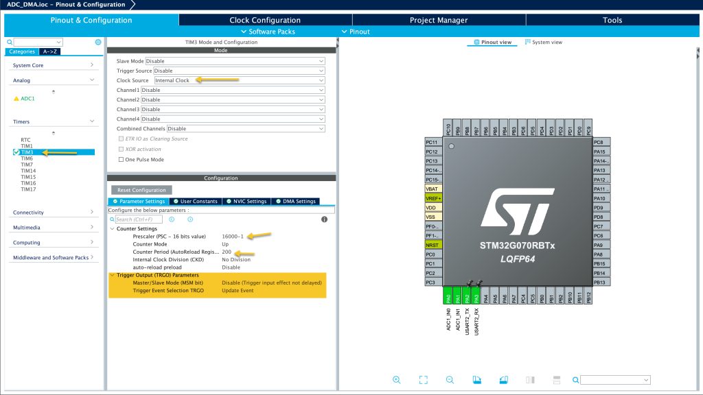
Set the timer as following:
- Set the prescaler to 16000-1.
- Set the period to 200-1, this will provide conversion each 200ms.
- Set trigger event selection to be update event.
Last, enable the UART to transmit data. Check this guide.
Thats all for the configuration. Save the project and this will generate the code.
In main.c:
We start off by including the stdio.h within user begin includes as following:
/* USER CODE BEGIN Includes */
#include "stdio.h"
/* USER CODE END Includes */
In user code begin PV, we shall declare the following two variables:
volatile uint8_t EndOfConversion;
uint16_t adc_data[2];
- EndOfConversion declare as volatile since this will changed within the interrupt handler.
- Array to hold the ADC converted data.
In user code begin 0, we shall retarget the printf to print directly to the serial terminal as following:
int __io_putchar(int ch)
{
	HAL_UART_Transmit(&huart2, &ch, 1, 10);
	return ch;
}
In user code begin 4, we shall declare the following function:
void HAL_ADC_ConvCpltCallback(ADC_HandleTypeDef *hadc)
{
	EndOfConversion=1;
}
This function shall be called once the ADC finishes the conversion and the DMA has transferred the data from ADC to the Memory.
Within the function, we shall set EndOfConversion to 1 to tell the application that the ADC has finished and the data is ready to be processed.
In user code begin 2, start the ADC in DMA mode:
HAL_ADC_Start_DMA(&hadc1, (uint32_t)&adc_data, 2);
Also, start the timer to trigger the ADC:
HAL_TIM_Base_Start(&htim3);
In user code begin 3 in while 1 loop:
- If EndOfConversion is set to 1, print the data and set it back to 0.
	  if(EndOfConversion==1)
	  {
		  printf("ADC CH0=%d ADC CH1=%d \r\n",adc_data[0],adc_data[1]);
		  EndOfConversion=0;
	  }
Thats all for the code.
Save the project, build and run it on your STM32G070.
3. Results:
Open your terminal, select the correct COM port and set the baudrate to be 115200 and you should get the following:

You have successfully triggered the ADC periodically and acquire the data using DMA.
Feel free to extend this project further.
Happy coding 😉
5 Comments
How to connect to you
Feel free to ask here.
great work
I have the same setup but with multiplexers attached to my adc channels and I cant get the buffer to fill accordingly. Where would you step the mux address in your example?
Hi,
show a schematic for your setup.
Add Comment