This guide focuses on implementing ADC oversampling on STM32 to improve resolution and reduce noise in analog signal acquisition. It explains the oversampling principle, hardware configuration, and how to leverage STM32’s built-in support for hardware averaging.
In this guide, we shall cover the following:
- What is oversampling.
- STM32CubeIDE setup for non-oversampling.
- Setup oversampling and calculation.
1. What is Oversampling:
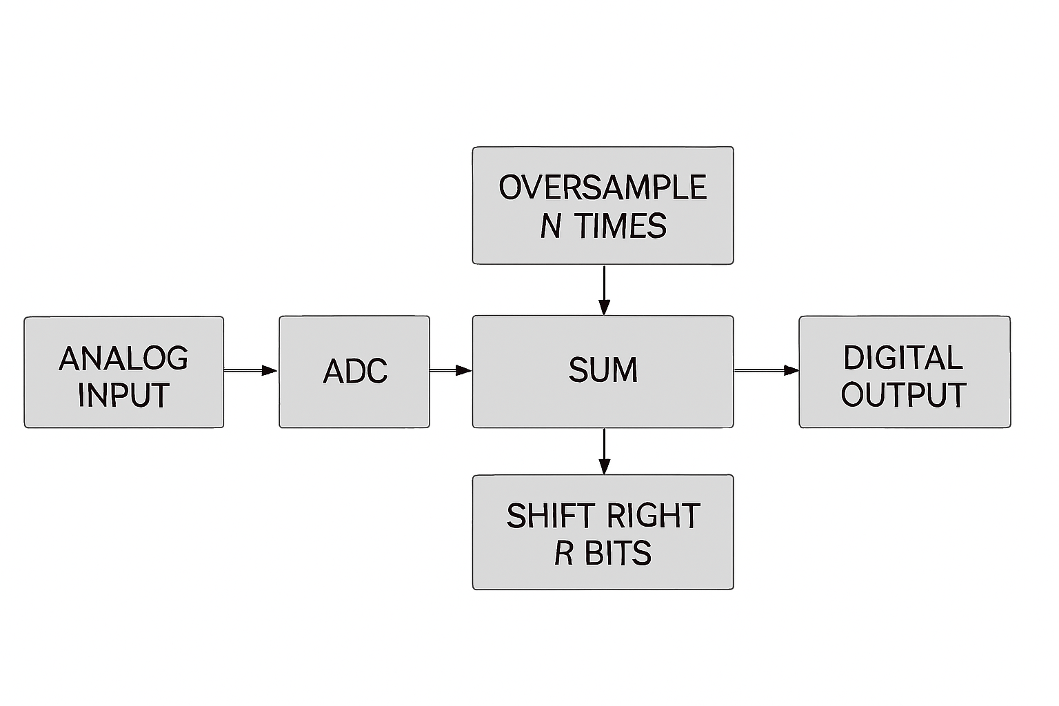
Oversampling is a powerful technique used in analog-to-digital conversion to improve the effective resolution and accuracy of ADC measurements without requiring higher-resolution hardware. In STM32 microcontrollers, including the STM32F4 series, oversampling involves taking multiple samples of the input signal at a faster rate and then averaging them to produce a single result with reduced noise and enhanced precision. This is especially useful in applications where signals are noisy or require high accuracy, such as in sensor measurements or audio processing.
The STM32 ADC hardware supports built-in oversampling capabilities (in some models) or it can be implemented in firmware when native support is limited. The principle relies on sampling the same analog input multiple times in quick succession and combining these readings—typically through summation and division (averaging) or bit shifting—to achieve a higher effective number of bits (ENOB). For instance, oversampling by a factor of 4 can theoretically increase the resolution by one extra bit. However, it’s important to ensure that the ADC input signal bandwidth is limited to avoid aliasing and that the acquisition window (sample time) is properly configured to maintain signal integrity.
To enable efficient and accurate oversampling, the sampling time of each ADC channel must be carefully selected to accommodate the source impedance and allow sufficient charging time for the internal sampling capacitor. Longer sample times can stabilize slow-changing or high-impedance signals, which is crucial when multiple oversampled readings are being taken consecutively.
In this guide, we’ll walk through how oversampling works in theory, what configuration options are available on STM32L4 devices, and what considerations to take into account regarding timing, conversion speed, and data handling. We’ll also include a block diagram of the oversampling process and provide guidance on setting up timers and DMA for more efficient sampling. The firmware development and implementation will be covered in a dedicated section.
2. STM32CubeIDE Setup for Non-oversampling:
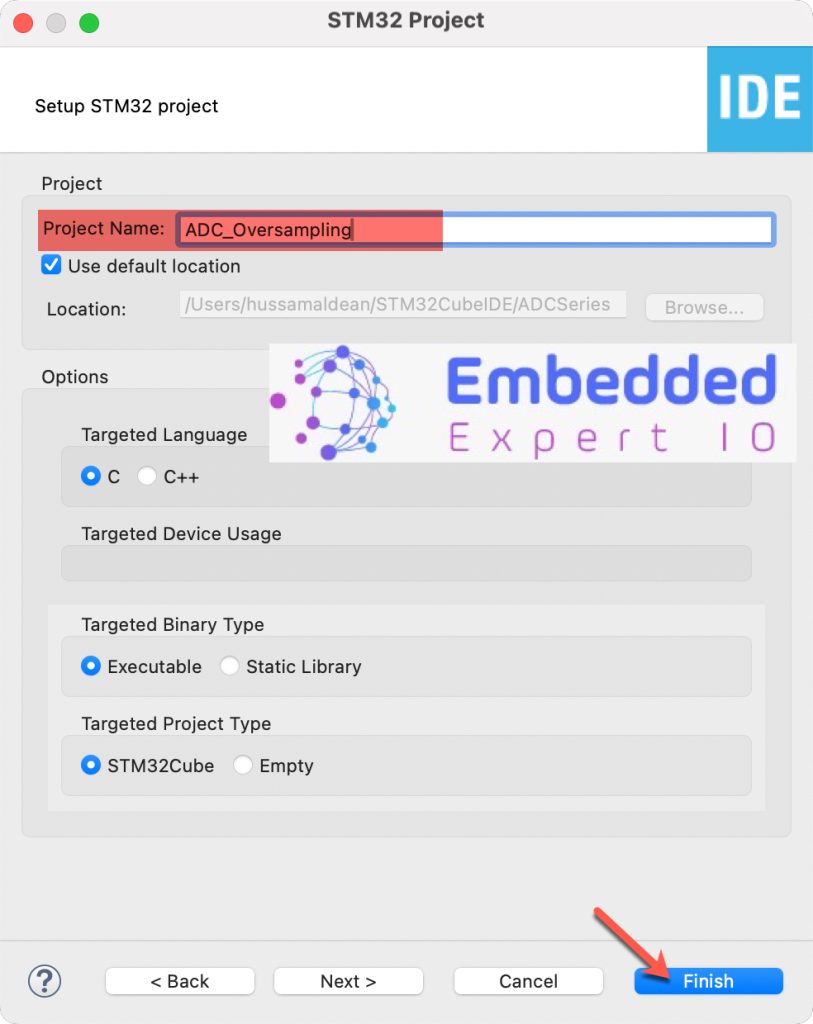
Open STM32CubeIDE after selecting the workspace and create new project as following:

Select the MCU (Ensure that you are selecting a one with oversampling like STM32L476RG):

Give the project a name:
Once the project has been created, STM32CubeMX window shall appear.
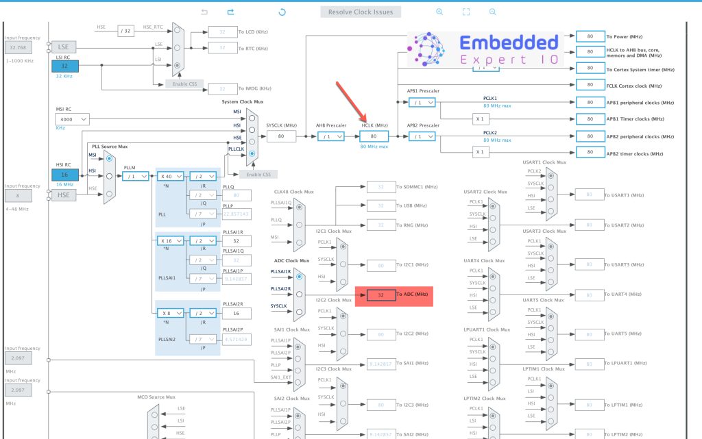
In Clock configuration, increase the system frequency to maximum and increase ADC clock to high value as follows (For STM32L476RG):
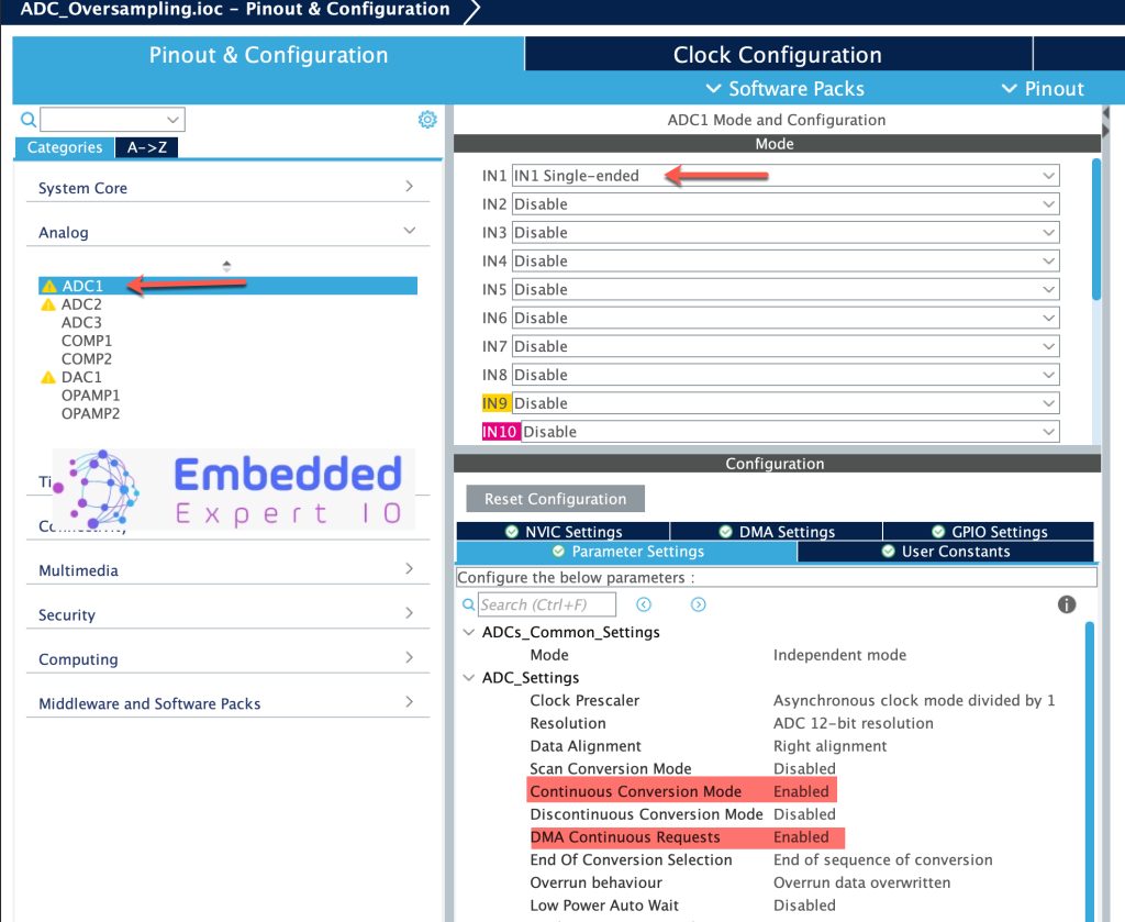
Next, Configure the ADC as follows:
- Enable any channel in single ended (Not all STM32 supports differential ADC input).
- Set conversion mode to continuous.
- Enable DMA continuous request (After enabling the DMA).
Next, enable configure the DMA as follows:
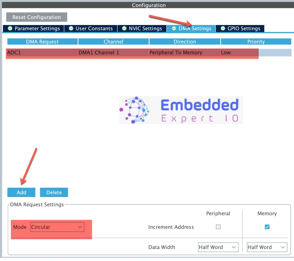
Also, enable any random pin as output (PA5 in this guide)
Thats all for the configuration. Save the project and this will generate the project.
Once the project is generated, main.c shall be opened.
In main.c in user code begin PV, declare the following array:
uint16_t adc_data[100]={0};The array shall hold 100 ADC samples (Needed to reduce the interrupt and measure time using GPIO toggle).
Next, in user code begin 0 declare the following function:
void HAL_ADC_ConvCpltCallback(ADC_HandleTypeDef* hadc)
{

		HAL_GPIO_TogglePin(GPIOA, GPIO_PIN_5);
}
Once the ADC has completed the 100 sample, ADC_ConvCpltCallback shall be called, within the callback, toggle the GPIO (PA5 in this case).
In user code begin 2 in main function, start the adc in the DMA mode:
HAL_ADC_Start_DMA(&hadc1, &adc_data, 100);
Save, build and debug the project.
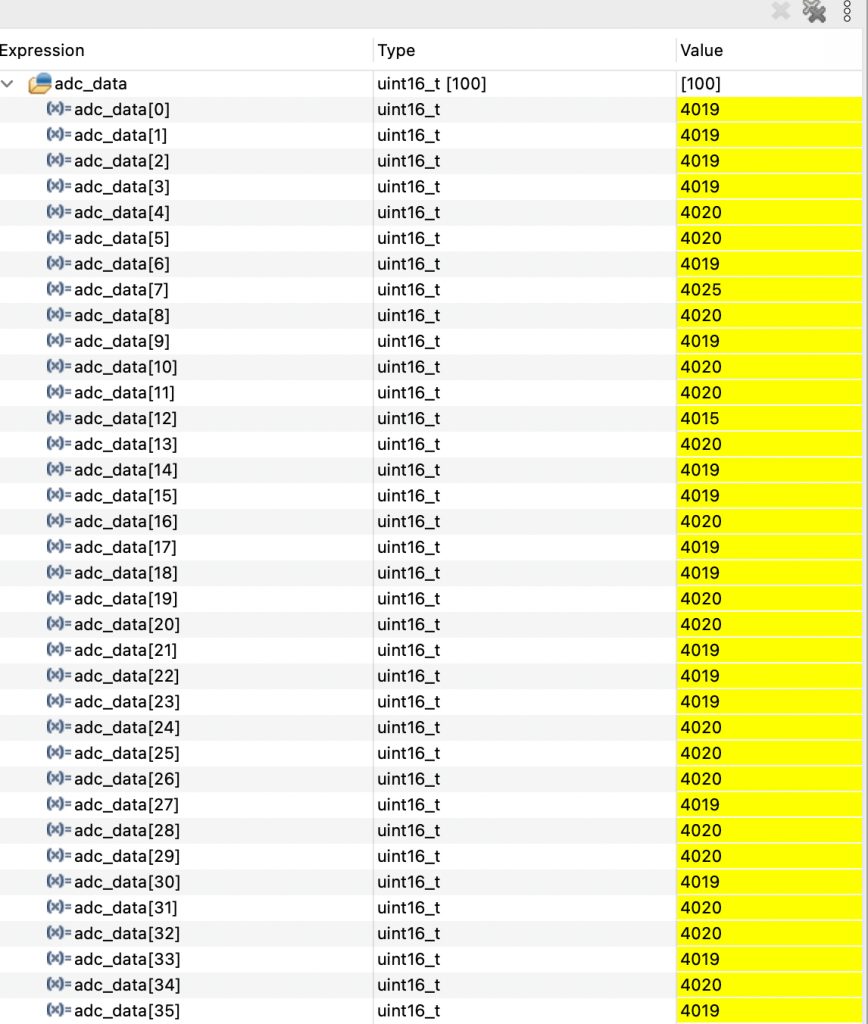
Add adc_data to the live expression and you should see the array are filling with ADC values as follows:
Here, the pin is connected to 3V3 and as you can see, we are getting 4020ish which is near the 4095 full ADC range.
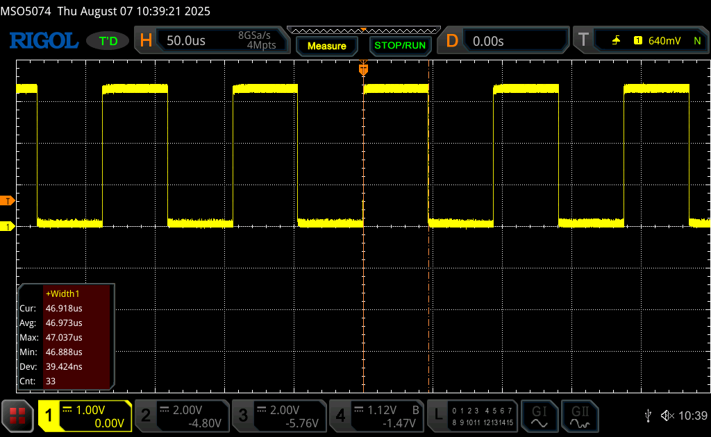
From the toggle pin:
From the STM32L476 reference manual:
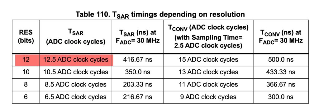
At 12-bit, the ADC need 12.5 ADC cycles to complete the conversion, also each channel requires 2.5 cycles (by default, can be changed in the configuration) which means total of 15 cycles.
By doing 15/32MHz, we get 0.468uS conversion time, since we are filling 100 samples, the time needed is 46.8 which is as shown in the oscilloscope screenshot.
3. Setup Oversampling and Calculation:
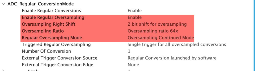
Open ADC_Oversample.ioc from project explorer and configure the ADC as follows:
- Enable oversampling.
- Set shift right to 2bit.
- Oversampling ratio to 64
To calculate the effective number of bit, the following formula is used:
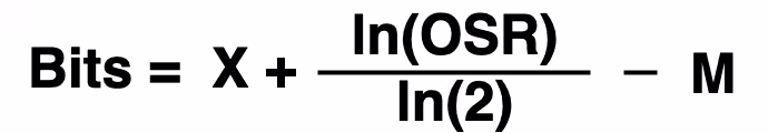
X is the ADC resolution (12-bit) OSR which is oversample ration (64 in this case) and M number of shifted bits which is 2.
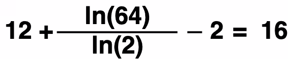
This will give us 16-bit effective resolution.
Save the project and this will generate the project.
Build the project and start a debug session and you should see the following:
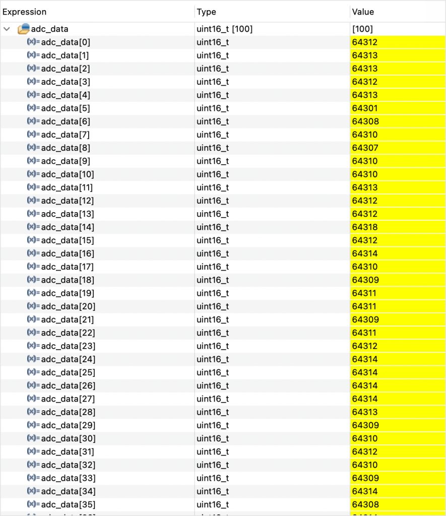
As you can see, we are getting the 16-bit ADC resolution despite the ADC is 12-bit.
However, this has a negative effect on the speed of the ADC.
From the oscilloscope screenshot:
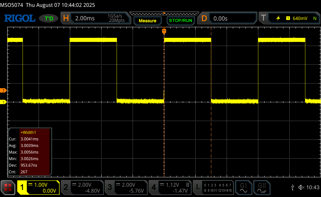
Note that the time has increased to 3ms to finish the 100 sample. Which means the ADC has been slowed down by a factor of 64 which is related to oversample ratio.
This means, the ADC has to sample the channel 64 times before moving to the next conversion.
Thats all.
Happy coding 😉
Add Comment