Timer interrupts in STM32 microcontrollers provide a powerful way to execute specific tasks at precise time intervals without continuous CPU polling. By leveraging timer interrupts, developers can create efficient and responsive embedded applications for tasks such as periodic data sampling, time-based event triggering, and real-time system scheduling.
In this guide, we shall cover the following:
- Introduction.
- STM32CubeIDE setup.
- Firmware development.
- Results.
1. Introduction:
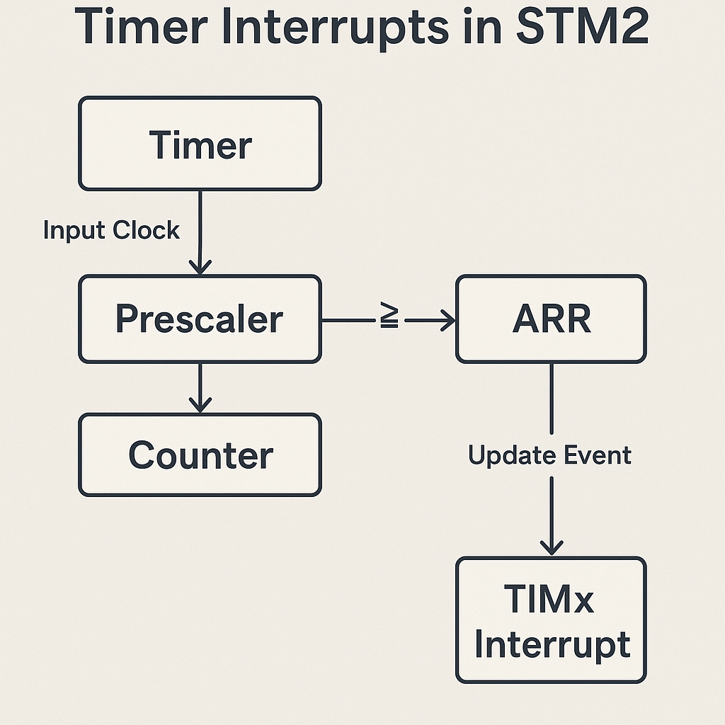
Timer interrupts are a fundamental feature in STM32 microcontrollers, providing a reliable and efficient method for executing time-critical tasks at precise intervals without burdening the CPU with continuous polling. By leveraging the hardware timers’ capability to generate update events upon reaching specific count values, timer interrupts allow developers to implement periodic operations with deterministic timing accuracy. This is particularly valuable in embedded systems where precise timing control is essential, such as in PWM signal generation, motor control loops, sensor sampling, communication protocol timing, or real-time scheduling in operating systems.
In practical applications, timer interrupts are widely used to create periodic tasks that maintain consistent execution rates regardless of other ongoing processes in the microcontroller. For example, an embedded application might use a timer interrupt to sample temperature sensors every 100 milliseconds, trigger ADC conversions at a fixed rate, toggle status LEDs with exact on/off durations, or increment software timers and counters required by the system. These tasks run independently of the main program loop, allowing the CPU to focus on higher-level operations while relying on hardware timers to maintain timing accuracy.
Another key advantage of using timer interrupts is their ability to offload timing management from software, resulting in improved system efficiency and reduced code complexity. Instead of using software delay loops or polling-based counters, which waste CPU cycles and can lead to unpredictable timing under heavy processing loads, timer interrupts execute only when triggered by the hardware event. This ensures real-time responsiveness even in complex or multitasking applications.
In STM32 microcontrollers, timers offer a rich set of configurations, including flexible prescalers, auto-reload registers, and multiple interrupt sources such as update events, capture/compare events, and trigger events. These features enable developers to tailor timer interrupt behavior to match specific application requirements, whether for millisecond-based periodic tasks or high-frequency interrupt-driven sampling. Additionally, timers can be synchronized with external signals, chained for extended timing ranges, or used in encoder interface mode, further expanding their utility in industrial control, robotics, instrumentation, and automation systems.
This section of the guide focuses on understanding the concept, benefits, and use cases of timer interrupts in embedded design. The detailed software implementation, including initialization, configuration, and example interrupt service routines, will be covered in subsequent sections.
2. STM32CubeIDE Setup:
Open STM32CubeIDE after selecting the workspace and create new project as following:

Select the MCU:

Give the project a name:
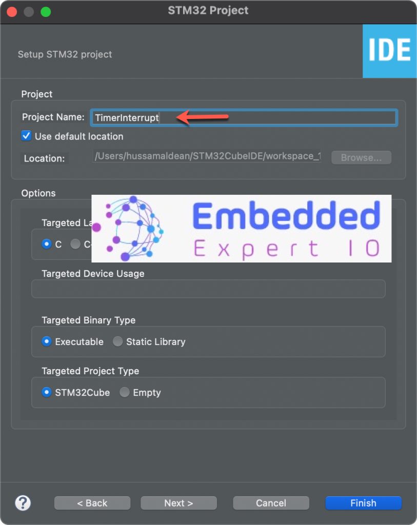
Click on Finish.
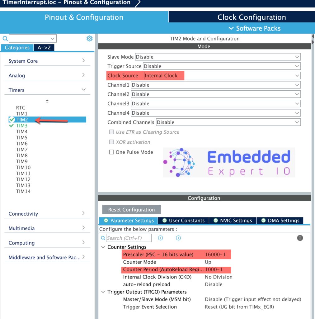
Next, STM32CubeMX window will appear, from timer configure TIM2 as follows:
- Set clock source to internal.
- Set Prescaler to 16000-1.
- Set the period to 1000-1.
This will make timer overflow each 1 second.
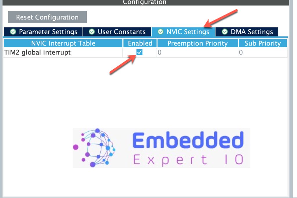
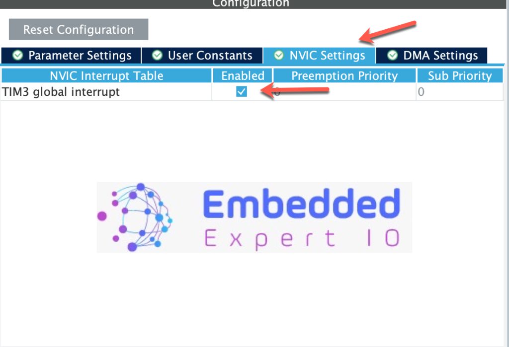
From NVIC settings, enable TIM2 interrupt:
Configure TIM3 as follows:
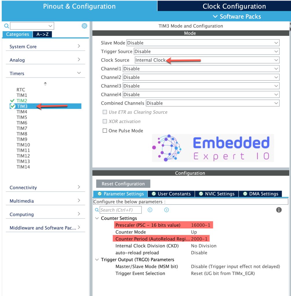
Note: The only difference between TIM2 and TIM3 is the period is 2000-1 rather than 1000-1 which will generate interrupt each 2 second rather than 1 second.
Save the project and this will generate the project.
3. Firmware Development:
Once the project has been generated, main.c shall be opened.
In main.c file, in user code begin PV (Private variable), declare the following two variables:
volatile uint32_t Tim2_Period,Tim3_Period;
Using volatile will let the compiler to not optimize the variable and it can be changed outside the code. Since we are using interrupt, we need to declare them as volatile.
Once the timer period elapsed, the following function shall be called:
void HAL_TIM_PeriodElapsedCallback(TIM_HandleTypeDef *htim)
This function will be called for each timer that his period has been elapsed.
Within the function, we shall check which timer has elapsed as follows:
if(htim->Instance==TIM2)
{
  Tim2_Period=HAL_GetTick();
}

if(htim->Instance==TIM3)
{
  Tim3_Period=HAL_GetTick();
}
We shall set the current tick in milliseconds to the variable according to which timer.
Hence, the function as follows:
void  HAL_TIM_PeriodElapsedCallback(TIM_HandleTypeDef *htim)
{
	if(htim->Instance==TIM2)
	{
		Tim2_Period=HAL_GetTick();
	}

	if(htim->Instance==TIM3)
	{
		Tim3_Period=HAL_GetTick();
	}

}
In user code begin 2 in the main function, start both timers in interrupt mode as follows:
  HAL_TIM_Base_Start_IT(&htim2);
  HAL_TIM_Base_Start_IT(&htim3);
Thats all for the firmware.
Build the project and run it.

4. Results:
In the debugging session, add Tim2_Period,Tim3_Period to live expression and you should get the following:
Note that Tim2_Period is incrementing every second while Tim3 is incrementing each 2 seconds which is as the setup in CubeMX.
Happy coding 😉
4 Comments
Dear Sir,
Greetings, Wishes,
I think this is the 400th Session in this site, in this series….
I am enjoying every lecture of your’s,
thanks with regards,
HSR-Rao.
Wait for more advanced topics on timers.
My TJC 4024 Is Burned Out Becouse I Connect 5+ To RX Pin
Can I Remove Stm32f030 And REplace STM32f103 ? Where the Farmware Is
It is nextion display, you can’t simply swap the chip without a proper flashing the firmware.
Just buy a new module.
Add Comment