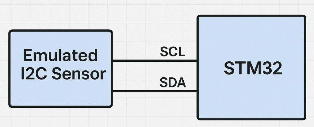
In this part of the guide, the emulated I2C sensor will handle incoming configuration data sent by the master device. This allows the STM32 to mimic a real sensor’s behavior by accepting register writes that define its operating mode and settings.
In this guide, we shall cover the following:
- Why the need for the configuration registers.
- Emulated sensor code.
- Master code.
- Results.
1. Why The Need For Configuration Registers:
Emulating the configuration-write path is just as important as emulating data reads, because almost every real I²C sensor must be configured before it will behave usefully. Here’s why it matters:
- Unblock development when hardware isn’t ready or available
Teams can bring up and test the master firmware (drivers, init sequences) even if the actual sensor is on back-order, expensive, or still being selected. - Validate real initialization sequences, not just happy-path reads
Real sensors require writes to mode, ODR, range, filter, and power registers before they output valid data. If your master mis-writes a bit, uses the wrong register pointer, or misses a repeated-start, the device won’t work. Emulation exposes these issues early. - Exercise complex write behaviors you’ll see in the field
- Multi-byte and auto-increment writes across page boundaries
- Repeated-start sequences (write register pointer → read back)
- Write-protected or “set/clear-on-write” bits
- Sticky status flags and “write-1-to-clear” semantics
- Banked register maps and undocumented reserved bits
- Robustness & error handling
You can deliberately NACK invalid registers, ignore illegal bit patterns, simulate time-dependent readiness, or require specific unlock keys—so the master’s error paths, retries, and timeouts are truly tested. - Timing realism
Some sensors don’t accept writes while busy (e.g., during NVM commit or measurement). Emulation lets you add realistic delays, clock stretching, and “busy until ready” states to validate the master’s patience and backoff logic. - Deterministic, reproducible tests
You can script exact sequences—valid, boundary, and pathological—and replay them in CI. That’s hard to do with real hardware that varies by lot, temperature, or prior state. - Security & safety scenarios
Inject malformed writes, unexpected STOPs, or mid-transaction bus errors to ensure the master fails safe, resets state machines, and never writes dangerous configs (e.g., disabling watchdogs). - System-level integration
On shared buses with multiple slaves, you can confirm the master addresses the right device, handles general-call behavior, coexists with other traffic, and respects bus recovery after glitches. - Manufacturing & diagnostics
A fixture with an emulated sensor can verify host boards on the line before expensive sensors are installed, and provide richer logs (exact bytes seen) than most physical sensors ever will. - Education & documentation
It’s a transparent way to teach register maps, endianness, repeated-start etiquette, ACK/NACK rules, and the difference between “transmit” (master→slave) vs “receive” (master reads).
In short, emulating configuration writes lets you prove that your master correctly addresses, sequences, times, validates, and persists sensor settings—turning a quick demo into a production-grade, testable integration.
2. Emulated Sensor Code:
In the main.c file of the i2c sensor emulation project , declare the following define as follows:
#define ConfigReg1 0x00

#define ConfigReg2 0x01
Here, we are assuming the sensor has two registers with address of 0x00 and 0x01 respectively. This will be part of configuration which shall be handled in later parts.
Next, declare two variables to hold the configuration data as follows:
uint8_t ConfigReg1Value=0;
uint8_t ConfigReg2Value=0;
This where the configuration data of ConfigReg1 and ConfigReg2 shall be stored.
Next, in HAL_I2C_SlaveRxCpltCallback function:
void HAL_I2C_SlaveRxCpltCallback(I2C_HandleTypeDef *hi2c)
{
	if(hi2c->Instance==I2C1)
	{
		if(RegisterData[0]==ConfigReg1)
		{
			ConfigReg1Value=RegisterData[1];
		}

		if(RegisterData[0]==ConfigReg2)
		{
			ConfigReg2Value=RegisterData[1];
		}
	}
}
This function shall be called when the slave the received the two bytes.
First, check if the interrupt from I2C1, if it is:
Check first byte if match ConfigReg1, store the second byte of the received data in ConfigReg1Value. In similar manner for ConfigReg2.
That all for the emulated sensor. Save the project and start a debugging session as follows:

3. Master Code:
In main.c of master project, in while 1 loop, we shall send the periodically as follows:
	  SlaveData[0]=0x00;
	  SlaveData[1]=(rand()%255);

	  HAL_I2C_Master_Transmit(&hi2c1, (0x1D<<1), &SlaveData, 2, 100);
	  HAL_Delay(100);

	  SlaveData[0]=0x01;
	  SlaveData[1]=(rand()%255);

	  HAL_I2C_Master_Transmit(&hi2c1, (0x1D<<1), &SlaveData, 2, 100);
	  HAL_Delay(100);
The transmitted data follows:
- First byte is the address of the configuration register.
- Second byte is the value to be written to the configuration register.
For now, we are still randomizing to validate the results.
Thats all for the master configuration. Save the project and run it on your MCU as follows:

4. Results:
By adding RegisterDat, ConfigReg1Value, ConfigReg2Value to the live expression, you should get something like this:
Stay tuned where in next part, we shall start developing the sensor and enable interrupt pin to tell the master there is new data and control the interrupt enable and sample rate.
Stay tuned and happy coding 😉
Add Comment