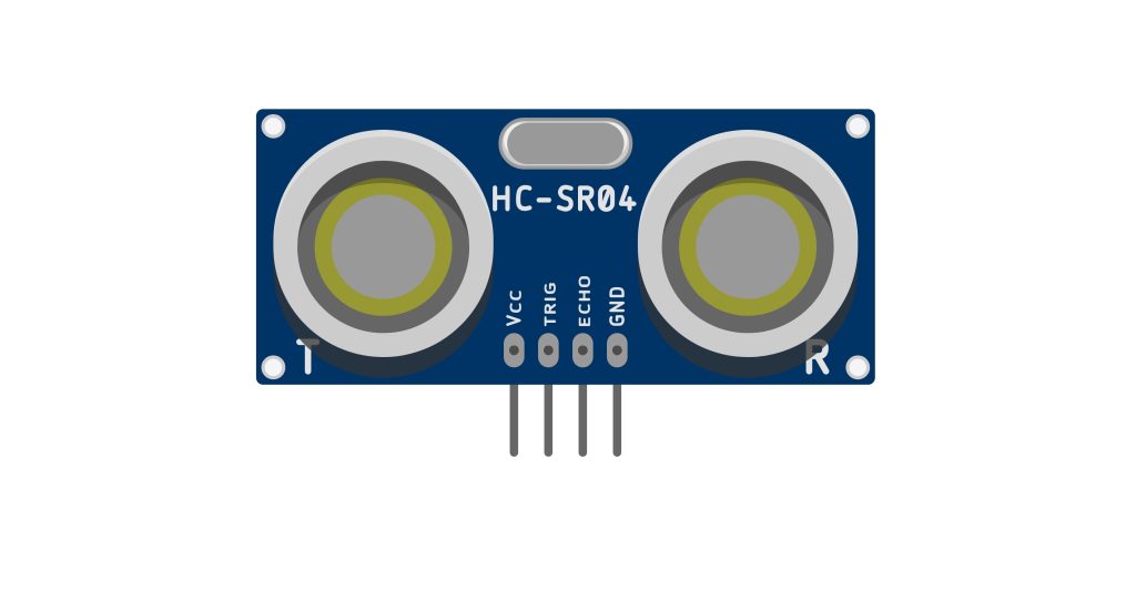
In part 1 of input capture guides, we shall see how to use input capture to measure the distance from an ultrasonic (HC-SR04) and display the measured distance on the serial terminal.
In this guide, we shall cover the following:
- What is input capture.
- HC-SR04 connection with STM32.
- Developing the driver.
- Code.
- Results.
1. What is input capture:
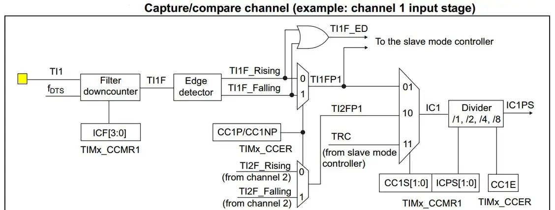
Each Capture/Compare channel is built around a capture/compare register (including a shadow register), an input stage for capture (with a digital filter, multiplexing, and Prescaler) and an output stage (with comparator and output control). The input stage samples the corresponding TIx input to generate a filtered signal TIxF. Then, an edge detector with polarity selection generates a signal (TIxFPx) which can be used as trigger input by the slave mode controller or as the capture command. It is prescaled before the capture register (ICxPS).
Here is a diagram for a capture/compare channel’s input stage.
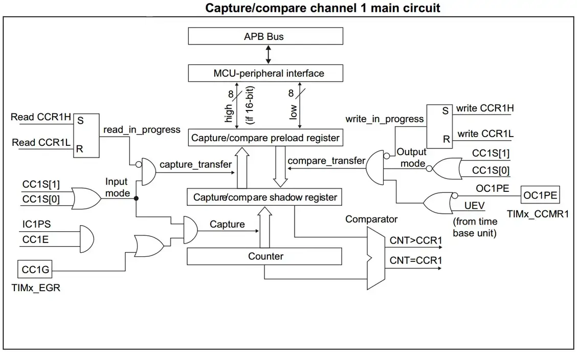
And here is a diagram for the capture/compare channel 1 Full Circuitry
STM32 Timers In Input Capture Mode
In Input capture mode, the Capture/Compare Registers (TIMx_CCRx) are used to latch the value of the counter after a transition detected by the corresponding ICx signal. When a capture occurs, the corresponding CCXIF flag (TIMx_SR register) is set and an interrupt or a DMA request can be sent if they are enabled. If a capture occurs while the CCxIF flag was already high, then the over-capture flag CCxOF (TIMx_SR register) is set. CCxIF can be cleared by software by writing it to 0 or by reading the captured data stored in the TIMx_CCRx register. CCxOF is cleared when written to 0. (source)
2. HC-SR04 Connection with STM32:
The connection as following:
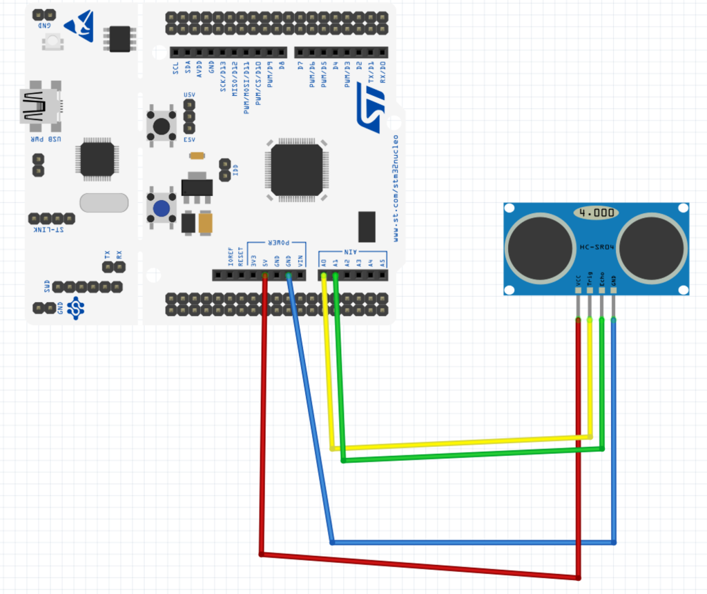
| HC-SR04 | STM32F411 Nucle0 |
| Vcc | 5V |
| GND | GND |
| Trig | PA0 |
| Echo | PA1 |
3. Developing the driver:
Before we develop the driver, take a look how the ultrasonic sensor works from here.
Also, take a look how to configure the pin as PWM from here.
How to configure a timer in input capture from here.
From the theory of how ultrasonic works, we need a pulse to trigger the sensor to start measure the distance. We can achieve this using PWM signal generated on PA0 and input capture mode on PA1.
We start off by declaring two variables:
- One to hold the measured pulse width.
- One to hold the measured distance.
/*Variable to hold the measured pulse length*/
uint32_t period;

/*variable to hold the measured distance*/
float distance;
Within the main function:
Enable floating point for float operation:
	/*Enable float point hardware*/
	SCB->CPACR |= ((3UL << 10*2)|(3UL << 11*2));
Set the core speed to be 100MHz: (check this guide for how to set it to 100MHz)
	/*Set the clock to 100MHz*/
	SysClockConfig();
Initialize the UART:
	/*Initialize UART2*/
	uart2_init();
Since we need two channels from timer2, we shall use PA0 and PA1 to generate the trigger signal and and measure the echo signal.
Start by enabling clock access to GPIOA as following:
	/*Enable clock access to GPIOA*/
	RCC->AHB1ENR|=RCC_AHB1ENR_GPIOAEN;
Set PA0 and PA1 as alternate function:
	/*Set PA0 and PA1 to alternate function*/
	GPIOA->MODER|=(GPIO_MODER_MODE0_1|GPIO_MODER_MODE1_1);
	GPIOA->MODER&=~(GPIO_MODER_MODE0_0|GPIO_MODER_MODE1_0);
Set the type of alternate function:
	/*Select AF01 for TIM2*/
	#define AF01 0x01
	GPIOA->AFR[0]|=(AF01<<GPIO_AFRL_AFSEL0_Pos)|(AF01<<GPIO_AFRL_AFSEL1_Pos);
Now, we shall configure timer2.
Start with enable clock access to TIM2 as following:
	/*enable clock access to tim2*/
	RCC->APB1ENR|=RCC_APB1ENR_TIM2EN;
Set the perscaler to 99: Since the timer clock running at 100MHz, with 99, we shall get 1MHz frequency
/*set the prescaler to 99 to get 1MHZ*/
TIM2->PSC=99;
Set the ARR to 999999 to get 1 second total period:
	/*set the maximum to 199999 to get 5 Hz update rate*/
	TIM2->ARR=1000000-1;
Reset the counter to ensure we start from zero:
	/*Reset current counter*/
	TIM2->CNT=0;
Set PA0 as PWM:
	/*Set PA0 as PWM*/
	TIM2->CCMR1|=TIM_CCMR1_OC1M_2| TIM_CCMR1_OC1M_1;
Set PA1 as input capture:
	/*Set PA1 as Input capture*/
	TIM2->CCMR1|=TIM_CCMR1_CC2S_0;
Enable both channel of the timer:
	/*Enable CH1 and CH2*/
	TIM2->CCER|=TIM_CCER_CC1E|TIM_CCER_CC2E;
Enable capture/compare for channel2 DMA request:
	/*Enable capture/compare 2 DMA*/
	TIM2->DIER|=TIM_DIER_CC2DE;
Set the trigger of the input to be both edge rising and falling:
	/*Set CH2 to be on both edge (falling/rising edge)*/
	TIM2->CCER|=TIM_CCER_CC2P|TIM_CCER_CC2NP;
Before enable the timer, we shall configure the DMA:
We start by enabling clock access to DMA1 as following:
	/*Enable clock access to DMA1*/

	RCC->AHB1ENR|=RCC_AHB1ENR_DMA1EN;
Disable the DMA stream and wait until it is disabled:
	/*Disable the stream and wait until it is disabled*/
	DMA1_Stream6->CR &=~DMA_SxCR_EN;

	while((DMA1_Stream6->CR & DMA_SxCR_EN) == DMA_SxCR_EN );
Configure the DMA1_Stream6 as following:
- Channel to be channel 3.
- Memory and peripheral size to be word size (32-bit).
- Circular mode.
	/*Configure the DMA with the following parameters
	 *
	 * Channel is channel 3
	 * Memory and peripheral size is word (32-bit)
	 * Circular mode
	 *
	 * */


	#define CH3 0x03

	DMA1_Stream6->CR |= (CH3<<DMA_SxCR_CHSEL_Pos)|DMA_SxCR_PSIZE_1|DMA_SxCR_MSIZE_1|DMA_SxCR_CIRC;
Set the DMA1 Stream6 to have those parameters also:
- Number of transfer to be 1.
- Peripheral address to be TIM2->CCR2.
- Memory address to be period.
	/*Set number of transfers to be 1
	 * Peripheral address to TIM2->CCR2
	 * Memory address to be the period variable
	 * */
	DMA1_Stream6->NDTR=1;
	DMA1_Stream6->PAR= (uint32_t)&TIM2->CCR2;
	DMA1_Stream6->M0AR=(uint32_t).
Give a delay of 30ms to ensure that ultrasonic is up and running:
	/*Delay to ensure the ultrasonic sensor is up*/
	delay(30);
Enable the DMA:
	/*Enable DMA*/
	DMA1_Stream6->CR |=DMA_SxCR_EN;
Enable the timer:
	/*Enable timer*/
	TIM2->CR1=TIM_CR1_CEN;
Generate 12 microsecond pulse:
	/*Give 12 microsecond pules to trigger pin*/
	TIM2->CCR1=12;
In while 1 loop:
Convert the period to distance as following:
/*calculate the distance*/

		distance=(float)((float)period-(float)538.0)*((float)0.034/(float)2);
Print the distance:
		/*Print the distance*/
		printf("Distance=%0.2f cm\r\n",distance);
Delay by half of second for uart stability:
		/*Delay between each print*/
		delay(500);
Hence, the entire code as following:
#include "delay.h"
#include "uart.h"
#include "stdio.h"
extern void SysClockConfig(void);
/*Variable to hold the measured pulse length*/
uint32_t period;
/*variable to hold the measured distance*/
float distance;
int main(void)
{
/*Enable float point hardware*/
SCB->CPACR |= ((3UL << 10*2)|(3UL << 11*2));
/*Set the clock to 100MHz*/
SysClockConfig();
/*Initialize UART2*/
uart2_init();
/*Enable clock access to GPIOA*/
RCC->AHB1ENR|=RCC_AHB1ENR_GPIOAEN;
/*Set PA0 and PA1 to alternate function*/
GPIOA->MODER|=(GPIO_MODER_MODE0_1|GPIO_MODER_MODE1_1);
GPIOA->MODER&=~(GPIO_MODER_MODE0_0|GPIO_MODER_MODE1_0);
/*Select AF01 for TIM2*/
#define AF01 0x01
GPIOA->AFR[0]|=(AF01<<GPIO_AFRL_AFSEL0_Pos)|(AF01<<GPIO_AFRL_AFSEL1_Pos);
/*enable clock access to tim2*/
RCC->APB1ENR|=RCC_APB1ENR_TIM2EN;
/*set the prescaler to 99 to get 1MHZ*/
TIM2->PSC=99;
/*set the maximum to 199999 to get 5 Hz update rate*/
TIM2->ARR=1000000-1;
/*Reset current counter*/
TIM2->CNT=0;
/*Set PA0 as PWM*/
TIM2->CCMR1|=TIM_CCMR1_OC1M_2| TIM_CCMR1_OC1M_1;
/*Set PA1 as Input capture*/
TIM2->CCMR1|=TIM_CCMR1_CC2S_0;
/*Enable CH1 and CH2*/
TIM2->CCER|=TIM_CCER_CC1E|TIM_CCER_CC2E;
/*Enable capture/compare 2 DMA*/
TIM2->DIER|=TIM_DIER_CC2DE;
/*Set CH2 to be on both edge (falling/rising edge)*/
TIM2->CCER|=TIM_CCER_CC2P|TIM_CCER_CC2NP;
/*DMA configuration*/
/*Enable clock access to DMA1*/
RCC->AHB1ENR|=RCC_AHB1ENR_DMA1EN;
/*Disable the stream and wait until it is disabled*/
DMA1_Stream6->CR &=~DMA_SxCR_EN;
while((DMA1_Stream6->CR & DMA_SxCR_EN) == DMA_SxCR_EN );
/*Configure the DMA with the following parameters
*
* Channel is channel 3
* Memory and peripheral size is word (32-bit)
* Circular mode
*
* */
#define CH3 0x03
DMA1_Stream6->CR |= (CH3<<DMA_SxCR_CHSEL_Pos)|DMA_SxCR_PSIZE_1|DMA_SxCR_MSIZE_1|DMA_SxCR_CIRC;
/*Set number of transfers to be 1
* Peripheral address to TIM2->CCR2
* Memory address to be the period variable
* */
DMA1_Stream6->NDTR=1;
DMA1_Stream6->PAR= (uint32_t)&TIM2->CCR2;
DMA1_Stream6->M0AR=(uint32_t).
/*Delay to ensure the ultrasonic sensor is up*/
delay(30);
/*Enable DMA*/
DMA1_Stream6->CR |=DMA_SxCR_EN;
/*Enable timer*/
TIM2->CR1=TIM_CR1_CEN;
/*Give 12 microsecond pules to trigger pin*/
TIM2->CCR1=12;
while(1)
{
/*calculate the distance*/
distance=(float)((float)period-(float)538.0)*((float)0.034/(float)2);
/*Print the distance*/
printf("Distance=%0.2f cm\r\n",distance);
/*Delay between each print*/
delay(500);
}
}4. Code:
You may download the code from here:
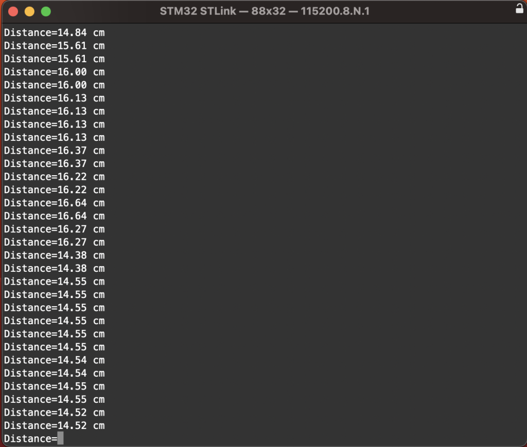
5. Results:
After uploading the code to your Nucleo-64 F411RE, open the serial terminal and set the baudrate to be 115200, you should get the following:
Happy coding 🙂
Add Comment