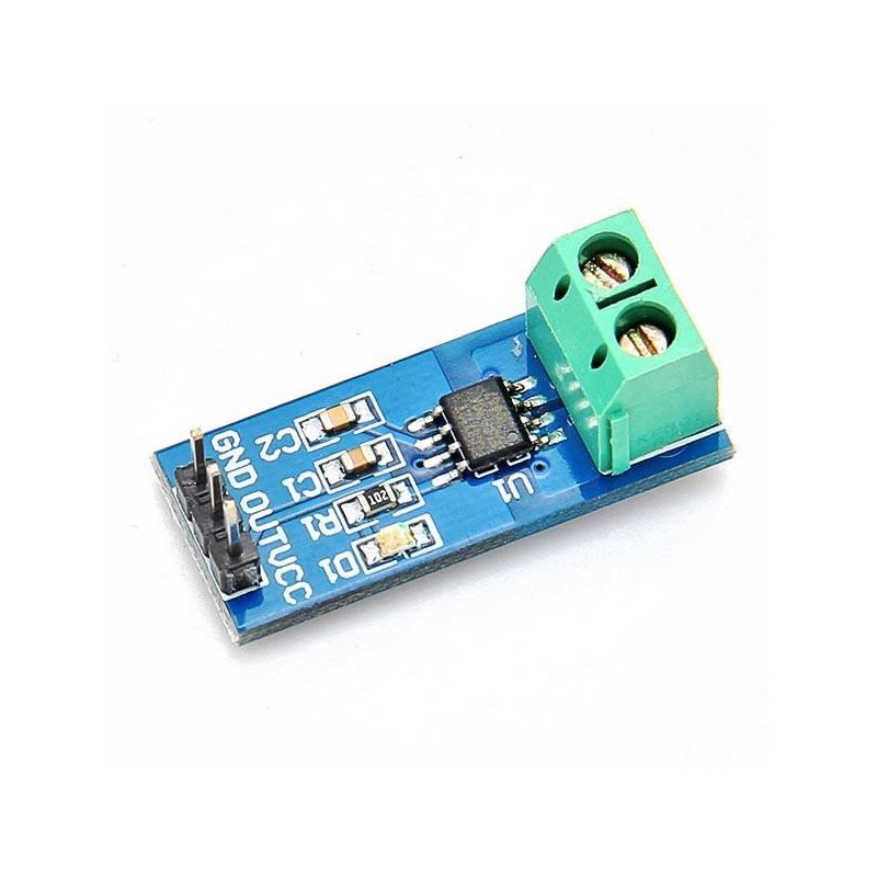
In the previous guide (here), we took a look at ACS712 current sensor and how to measure DC current. In this guide we shall use this sensor to measure AC current.
NOTE: This guide uses main voltages. Please handle with care
In this guide, we shall cover the following:
- What is RMS in AC.
- ACS712 connection with main.
- ACS712 connection with STM32F4.
- Driver development.
- Code.
- Results.
1. What RMS in AC:
The term “RMS” stands for “Root-Mean-Squared”. Most books define this as the “amount of AC power that produces the same heating effect as an equivalent DC power”, or something similar along these lines, but an RMS value is more than just that.
The term “RMS” stands for “Root-Mean-Squared”. Most books define this as the “amount of AC power that produces the same heating effect as an equivalent DC power”, or something similar along these lines, but an RMS value is more than just that.
The RMS value is the square root of the mean (average) value of the squared function of the instantaneous values. The symbols used for defining an RMS value are VRMS or IRMS.
The term RMS, ONLY refers to time-varying sinusoidal voltages, currents or complex waveforms were the magnitude of the waveform changes over time and is not used in DC circuit analysis or calculations were the magnitude is always constant.
When used to compare the equivalent RMS voltage value of an alternating sinusoidal waveform that supplies the same electrical power to a given load as an equivalent DC circuit, the RMS value is called the “effective value” and is generally presented as: Veff or Ieff.
In other words, the effective value is an equivalent DC value which tells you how many volts or amps of DC that a time-varying sinusoidal waveform is equal to in terms of its ability to produce the same power.
For example, the domestic mains supply in the United Kingdom is 240Vac. This value is assumed to indicate an effective value of “240 Volts rms”. This means then that the sinusoidal rms voltage from the wall sockets of a UK home is capable of producing the same average positive power as 240 volts of steady DC voltage as shown below.
RMS Voltage Equivalent

2. ACS712 connection with main:
The connection as following:
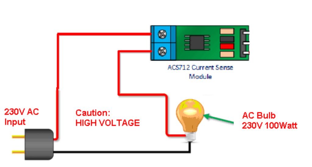
Please handle mains voltage with care.
3. ACS712 connection with STM32F4:
The connection of I2C LCD and ACS712 Current sensor module as following:
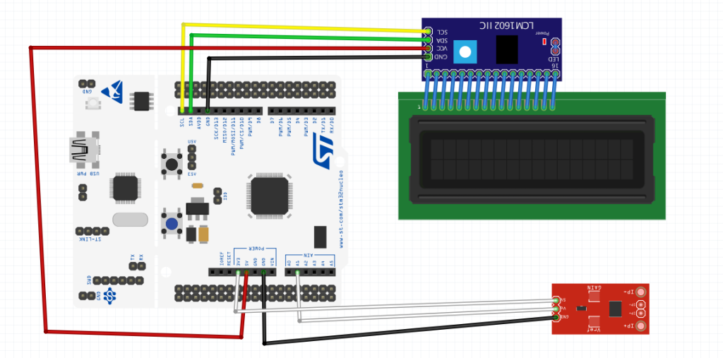
| ACS712 | STM32F4xx |
| Vcc | 3V3 |
| Vout | PA1 |
| GND | GND |
4. Driver development:
In this guide, we shall use ADC with DMA in double buffer mode and to be triggered using timer. For more details check this guide here.
Also, Kalman filter is used to obtain stable noiseless results, please refer to this guide about Kalman filter.
First, we shall declare two arrays with size of 100:
#define size_of_data 100


uint16_t current_data1[size_of_data];

uint16_t current_data2[size_of_data];
When the second array is being filled, we shall process the fist one.
extra variables needed:
float calc,result;

float current_result, current_previous;
Define the offset which is the raw adc value when no current is applied due to hall effect:
#define offset 2010
In this case, it is 2010 (change according to your needing)>
For acs712 initializing, the following steps are required:
- Enable floating point unit.
- Set PA1 as analog mode.
- Configure ADC to work in DMA and triggered using timer.
- Configure DMA in double buffer mode and half transfer interrupt.
Enabling FPU:
	/*Enable floating point unit:  Enable CP10 and CP11 full access*/
	SCB->CPACR |=(1<<20);
	SCB->CPACR |=(1<<21);
	SCB->CPACR |=(1<<22);
	SCB->CPACR |=(1<<23);
Set PA1 as analog mode:
	RCC->AHB1ENR|=RCC_AHB1ENR_GPIOAEN; //enable gpio a clock
	GPIOA->MODER|=GPIO_MODER_MODER1;  //set the PA1 to analog mode
ADC setup:
/*ADC related set up*/

	RCC->APB2ENR		|=RCC_APB2ENR_ADC1EN;
	ADC1->CR2			|=ADC_CR2_DMA|ADC_CR2_DDS;
	ADC1->CR2			|=ADC_CR2_EXTEN_0;
	ADC1->CR2			|=ADC_CR2_EXTSEL_1|ADC_CR2_EXTSEL_2;
	ADC1->SQR3			|=(1<<ADC_SQR3_SQ1_Pos);
	ADC1->SMPR2			|=(0x07<<ADC_SMPR2_SMP1_Pos);
DMA setup:
/*DMA related setup*/
	RCC->AHB1ENR		|=RCC_AHB1ENR_DMA2EN;
	DMA2_Stream0->CR	&=~DMA_SxCR_EN;

	while(DMA2_Stream0->CR ==DMA_SxCR_EN){;}

	DMA2_Stream0->CR	|=DMA_SxCR_MSIZE_0|DMA_SxCR_PSIZE_0|DMA_SxCR_MINC|DMA_SxCR_HTIE|DMA_SxCR_CIRC|DMA_SxCR_DBM;

	DMA2_Stream0->PAR	 =(uint32_t)(&(ADC1->DR));

	DMA2_Stream0->M0AR 	 =(uint32_t )(current_data1);

	DMA2_Stream0->M1AR 	 =(uint32_t )(current_data2);

	DMA2_Stream0->NDTR	 =size_of_data;

	NVIC_EnableIRQ(DMA2_Stream0_IRQn);
Timer setup:
	/* Timer related setup*/
	RCC->APB1ENR		|=RCC_APB1ENR_TIM2EN;
	TIM2->PSC			 =1600-1;
	TIM2->ARR			 =10-1;
	TIM2->CR2			|=TIM_CR2_MMS_1;
Launching everything:
	/*Launch the ADC*/
	ADC1->CR2			|=ADC_CR2_ADON;
	/*Launch the DMA*/
	DMA2_Stream0->CR 	|=DMA_SxCR_EN;
	/*Launch the timer*/
	TIM2->CR1			|=TIM_CR1_CEN;
For interrupt handler:
- Check interrupt source if it is half transfer, set finished to 1 and clear the pending flag:
void DMA2_Stream0_IRQHandler(void)
{

	if(((DMA2->LISR)&DMA_LISR_HTIF0))
	{
		finished=1;
		DMA2->LIFCR=DMA_LIFCR_CHTIF0;
		}
		NVIC_ClearPendingIRQ(DMA2_Stream0_IRQn);
	}
For getting the current:
float get_acs712_current()
{
	if(finished==1)
	{
		finished=0;

		if((DMA2_Stream0->CR & DMA_SxCR_CT)>> DMA_SxCR_CT_Pos == 1 )
		{
			return calculate_rms(current_data2);
		}

		else
		{
			return calculate_rms(current_data1);
		}

	}

	else
	{
		return current_previous;
	}

}
First check if DMA finshed filling the buffer by checking finished, if it is:
The following steps are performed:
- Set finished to 0.
- Check the CT bit and see which buffer is used and process the buffer accordingly.
If the DMA has not yet finished the filling process, return previous values.
RSM calculation:
The equation to calculate the RMS is as following:
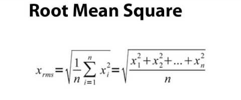
We need to summation of values squared then divide by number of samples and then the square root of the final value.
Hence, the function as following:
static float calculate_rms(uint16_t * values)
{
	calc=0;
	for (int i=0;i<size_of_data;i++)
	{
		calc=calc+((values[i]-offset) * (values[i]-offset));
	}
	calc=calc/size_of_data;
	calc=sqrt(calc);

	result=kalman_filter(calc);
	result=0.0206*result-0.2;
	current_previous=result;
	return result;
}
The steps as following:
- Reset the calc variable.
- Multiply the current values minus the offset and added to previous calc value using for loop.
- Divide the result by number of samples.
- Take the square root of the result and store it in calc.
- Store the filtered calc value into result.
- Store the current result in current_previous.
- Return the result.
For the kalman filter:
static float kalman_filter(float RMS_Value)
{
    float x_k1_k1,x_k_k1;

    static float RMS_OLD_Value=0;

    float Z_k;

    static float P_k1_k1;

    static float Q = 0.01;//Q: Regulation noise, Q increases, dynamic response becomes faster, and convergence stability becomes worse
    static float R = 0.5; //R: Test noise, R increases, dynamic response becomes slower, convergence stability becomes better
    static float Kg = 0;
    static float P_k_k1 = 1;

    float kalman_rms;
    static float kalman_rms_old=0;
    Z_k = RMS_Value;
    x_k1_k1 = kalman_rms_old;

    x_k_k1 = x_k1_k1;
    P_k_k1 = P_k1_k1 + Q;

    Kg = P_k_k1/(P_k_k1 + R);

    kalman_rms = x_k_k1 + Kg * (Z_k - kalman_rms_old);
    P_k1_k1 = (1 - Kg)*P_k_k1;
    P_k_k1 = P_k1_k1;

    RMS_OLD_Value = RMS_Value;
    kalman_rms_old = kalman_rms;

    return kalman_rms;
}
Hence, the entire source code as following:
#include "stm32f4xx.h"
#include "acs712.h"
#include "math.h"


float calc,result;

#define size_of_data 100


uint16_t current_data1[size_of_data];

uint16_t current_data2[size_of_data];


volatile uint8_t finished;

#define offset 2010


float current_result, current_previous;


void acs712_init()
{
	/*Enable floating point unit:  Enable CP10 and CP11 full access*/
	SCB->CPACR |=(1<<20);
	SCB->CPACR |=(1<<21);
	SCB->CPACR |=(1<<22);
	SCB->CPACR |=(1<<23);

	RCC->AHB1ENR|=RCC_AHB1ENR_GPIOAEN; //enable gpio a clock
	GPIOA->MODER|=GPIO_MODER_MODER1;  //set the PA1 to analog mode


	/*ADC related set up*/

	RCC->APB2ENR		|=RCC_APB2ENR_ADC1EN;
	ADC1->CR2			|=ADC_CR2_DMA|ADC_CR2_DDS;
	ADC1->CR2			|=ADC_CR2_EXTEN_0;
	ADC1->CR2			|=ADC_CR2_EXTSEL_1|ADC_CR2_EXTSEL_2;
	ADC1->SQR3			|=(1<<ADC_SQR3_SQ1_Pos);
	ADC1->SMPR2			|=(0x07<<ADC_SMPR2_SMP1_Pos);

	/*DMA related setup*/
	RCC->AHB1ENR		|=RCC_AHB1ENR_DMA2EN;
	DMA2_Stream0->CR	&=~DMA_SxCR_EN;

	while(DMA2_Stream0->CR ==DMA_SxCR_EN){;}

	DMA2_Stream0->CR	|=DMA_SxCR_MSIZE_0|DMA_SxCR_PSIZE_0|DMA_SxCR_MINC|DMA_SxCR_HTIE|DMA_SxCR_CIRC|DMA_SxCR_DBM;

	DMA2_Stream0->PAR	 =(uint32_t)(&(ADC1->DR));

	DMA2_Stream0->M0AR 	 =(uint32_t )(current_data1);

	DMA2_Stream0->M1AR 	 =(uint32_t )(current_data2);

	DMA2_Stream0->NDTR	 =size_of_data;

	NVIC_EnableIRQ(DMA2_Stream0_IRQn);

	/* Timer related setup*/
	RCC->APB1ENR		|=RCC_APB1ENR_TIM2EN;
	TIM2->PSC			 =1600-1;
	TIM2->ARR			 =10-1;
	TIM2->CR2			|=TIM_CR2_MMS_1;


	/*Launch the ADC*/
	ADC1->CR2			|=ADC_CR2_ADON;
	/*Launch the DMA*/
	DMA2_Stream0->CR 	|=DMA_SxCR_EN;
	/*Launch the timer*/
	TIM2->CR1			|=TIM_CR1_CEN;

}


static float kalman_filter(float RMS_Value)
{
    float x_k1_k1,x_k_k1;

    static float RMS_OLD_Value=0;

    float Z_k;

    static float P_k1_k1;

    static float Q = 0.01;//Q: Regulation noise, Q increases, dynamic response becomes faster, and convergence stability becomes worse
    static float R = 0.5; //R: Test noise, R increases, dynamic response becomes slower, convergence stability becomes better
    static float Kg = 0;
    static float P_k_k1 = 1;

    float kalman_rms;
    static float kalman_rms_old=0;
    Z_k = RMS_Value;
    x_k1_k1 = kalman_rms_old;

    x_k_k1 = x_k1_k1;
    P_k_k1 = P_k1_k1 + Q;

    Kg = P_k_k1/(P_k_k1 + R);

    kalman_rms = x_k_k1 + Kg * (Z_k - kalman_rms_old);
    P_k1_k1 = (1 - Kg)*P_k_k1;
    P_k_k1 = P_k1_k1;

    RMS_OLD_Value = RMS_Value;
    kalman_rms_old = kalman_rms;

    return kalman_rms;
}


static float calculate_rms(uint16_t * values)
{
	calc=0;
	for (int i=0;i<size_of_data;i++)
	{
		calc=calc+((values[i]-offset) * (values[i]-offset));
	}
	calc=calc/size_of_data;
	calc=sqrt(calc);

	result=kalman_filter(calc);
	result=0.0206*result-0.2;
	current_previous=result;
	return result;
}


float get_acs712_current()
{
	if(finished==1)
	{
		finished=0;

		if((DMA2_Stream0->CR & DMA_SxCR_CT)>> DMA_SxCR_CT_Pos == 1 )
		{
			return calculate_rms(current_data2);
		}

		else
		{
			return calculate_rms(current_data1);
		}

	}
	else
	{
		return current_previous;
	}
}


void DMA2_Stream0_IRQHandler(void)
{

	if(((DMA2->LISR)&DMA_LISR_HTIF0))
	{
		finished=1;
		DMA2->LIFCR=DMA_LIFCR_CHTIF0;
		}
		NVIC_ClearPendingIRQ(DMA2_Stream0_IRQn);
	}
main.c:
#include "stdio.h"
#include "delay.h"
#include "lcd.h"
#include "i2c.h"

#include "acs712.h"

float current_value;

char curr_data[15];
int main(void)
{
	i2c_init();
	systick_init_ms(16000000);
	lcd_init();
	acs712_init();

	while(1)
	{

		current_value=get_acs712_current();
		if(millis()%400==0){
		setCursor(0,0);
		lcd_send_string("AC Current=");
		sprintf(curr_data,"%0.3f   ",current_value);
		setCursor(0,1);
		lcd_send_string(curr_data);}

	}
}
5. Code:
You may download the entire source code from here:
6. Results:
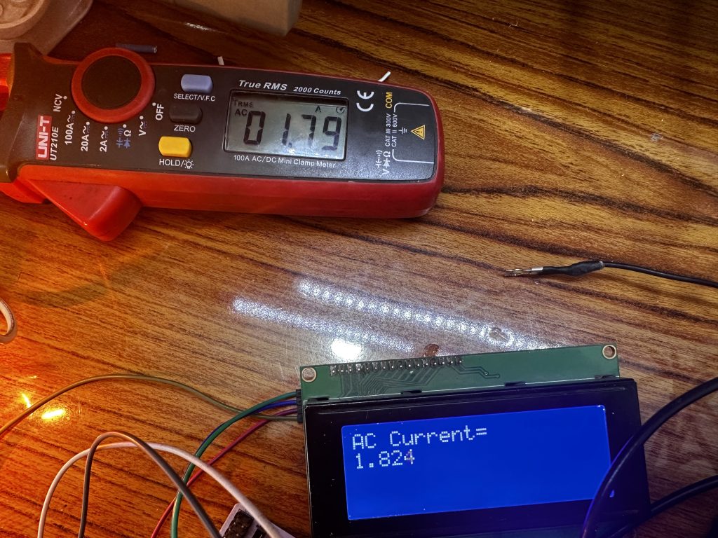
Happy coding 🙂
4 Comments
hello Husamuldeen
While driving a 3-phase BLDC motor with a PWM invertor, should the current reading be made with an AC sensor or a DC sensor?
Check a well made bldc motor and how the current is being measured.
ADC1->SQR3 |=(1<SMPR2 |=(0x07<<ADC_SMPR2_SMP1_Pos);
What should we write instead of pos?
ADC_SQR3_SQ1_Pos = ADC_SQR3_SQ1_0*30
0x07<<ADC_SMPR2_SMP1_Pos= ADC_SMPR2_SMP1_0*10
is it possible?
Elaborate further please.
Add Comment