In this guide, we shall see how to configure the timer to work as input capture mode.
In this guide we shall cover the following:
- Input Capture Mode.
- Connection.
- Code.
- Results.
1. Input Capture Mode:
As we’ve discussed in an earlier tutorial, the timer modules can operate a variety of modes one of which is the input capture mode. Where the timer gets clocked from an internal source and its current value is captured and saved to the input capture register whenever a special event occurs on the input capture channel pin. Here is a brief description of the capture compare channels in STM32 timers modules. And also note that every single timer module has multiple (input capture/compare output) channels (3, 4, 6, or whatever found in the datasheet).
STM32 Timers – Capture/Compare Channels
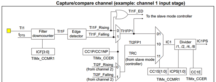
Each Capture/Compare channel is built around a capture/compare register (including a shadow register), an input stage for capture (with a digital filter, multiplexing, and Prescaler) and an output stage (with comparator and output control). The input stage samples the corresponding TIx input to generate a filtered signal TIxF. Then, an edge detector with polarity selection generates a signal (TIxFPx) which can be used as trigger input by the slave mode controller or as the capture command. It is prescaled before the capture register (ICxPS).
Here is a diagram for a capture/compare channel’s input stage.
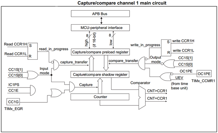
And here is a diagram for the capture/compare channel 1 Full Circuitry
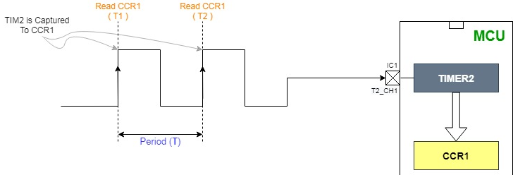
STM32 Timers In Input Capture Mode
In Input capture mode, the Capture/Compare Registers (TIMx_CCRx) are used to latch the value of the counter after a transition detected by the corresponding ICx signal. When a capture occurs, the corresponding CCXIF flag (TIMx_SR register) is set and an interrupt or a DMA request can be sent if they are enabled. If a capture occurs while the CCxIF flag was already high, then the over-capture flag CCxOF (TIMx_SR register) is set. CCxIF can be cleared by software by writing it to 0 or by reading the captured data stored in the TIMx_CCRx register. CCxOF is cleared when written to 0.
2. Connection:
We shall use OLED display to display time base as following:
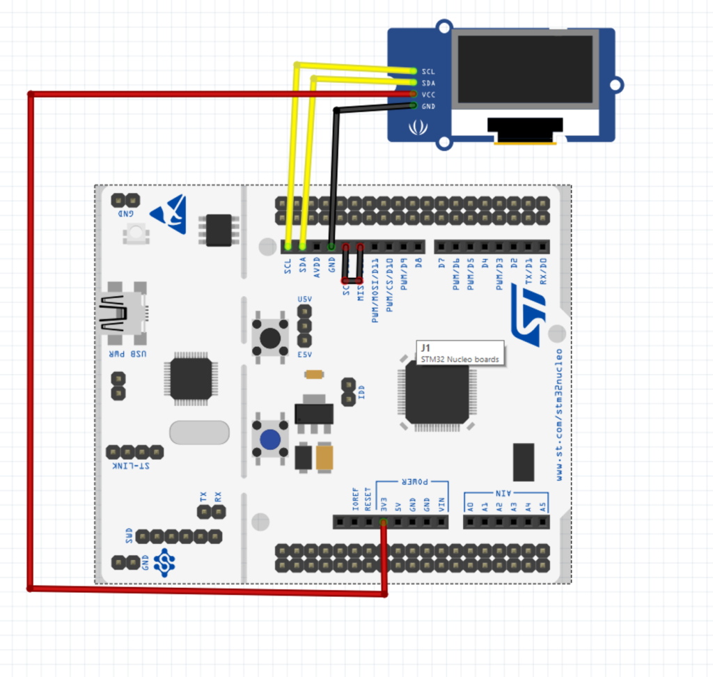
Also, a jumper wire shall be connected between PA5 and PA6 (D13&D12 in case of F411 Nucleo).
3. Code:
Fist we set PA5 as output compare to toggle the LED at rate of 0.5Hz (from here)
Next we set PA6 which is connected to TIM3 as input capture.
We start by enable clock access to GPIOA and set PA6 to alternative function and TIM3 alternative function as following:
RCC->AHB1ENR |=RCC_AHB1ENR_GPIOAEN;
GPIOA->MODER &=~GPIO_MODER_MODE6_0;
GPIOA->MODER |=GPIO_MODER_MODE6_1;
#define AFR6_TIM	(1U<<25)
GPIOA->AFR[0] |=AFR6_TIM;
After that we enable clock access to TIM3 as following as set prescaller to 16000-1:
RCC->APB1ENR |=RCC_APB1ENR_TIM3EN;
TIM3->PSC = 16000 -1; // 16 000 000 /16 000
After than we configure channel1 of TIM3 to input:
	/*Set CH1 to input capture*/
	TIM3->CCMR1  = CCER_CC1S;

	/*Set CH1 to capture at rising edge*/
	TIM3->CCER  = CCER_CC1E;
And finally enable timer:
	/*Enable TIM3*/
	TIM3->CR1 = CR1_CEN;
In the main file, we can wait for SR_CC1IF to be set as following:
		while(!(TIM3->SR & SR_CC1IF)){}

		/*Read captured value*/
		timestamp =  TIM3->CCR1;
you may download the code from here:
4. Results:
Happy coding 🙂
2 Comments
I understand the CC1S bits of the TIM1’s CCMR1 register selects the input to capture.. but where does it say that TIM2 is connected to CC1S?
For example, could you measure an external frequency? What register value would change? And would the input pin be (the normally output) TIM3 CH1?
Yes, you can.
Just convert the time to frequency f=1/t;
Regarding CC1s, it is available for all timers that support PWM mode.
Add Comment