In this guide, we shall interface ACS712 hall effect current sensor with STM32.
In this guide, we shall cover the following:
- ACS712 Sensor.
- Connection.
- Driver Development.
- Code.
- Result.
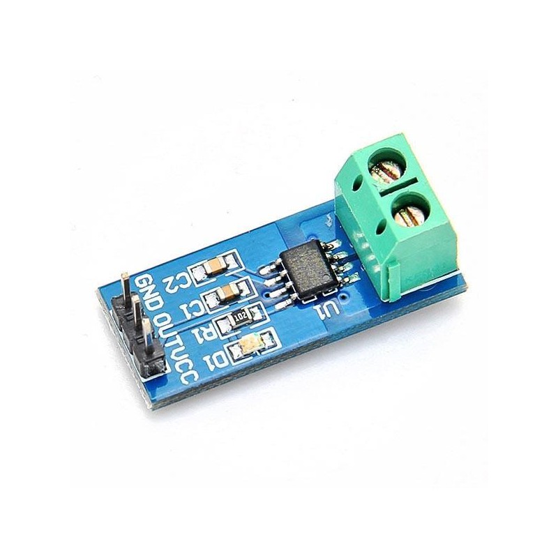
1. ACS712 Sensor:
The Allegro® ACS712 provides economical and precise solutions for AC or DC current sensing in industrial, commercial, and communications systems. The device package allows for easy implementation by the customer. Typical applications include motor control, load detection and management, switched-mode power supplies, and overcurrent fault protection.
The device consists of a precise, low-offset, linear Hall sensor circuit with a copper conduction path located near the surface of the die. Applied current flowing through this copper conduction path generates a magnetic field which is sensed by the integrated Hall IC and converted into a proportional voltage. Device accuracy is optimized through the close proximity of the magnetic signal to the Hall transducer. A precise, proportional voltage is provided by the low-offset, chopper-stabilized BiCMOS Hall IC, which is programmed for accuracy after packaging.
The output of the device has a positive slope (>VIOUT(Q)) when an increasing current flows through the primary copper conduction path (from pins 1 and 2, to pins 3 and 4), which is the path used for current sensing. The internal resistance of this conductive path is 1.2 mΩ typical, providing low power loss. The thickness of the copper conductor allows survival of the device at up to 5× overcurrent conditions. The terminals of the conductive path are electrically isolated from the sensor leads (pins 5 through 8). This allows the ACS712 current sensor to be used in applications requiring electrical isolation without the use of opto-isolators or other costly isolation techniques.
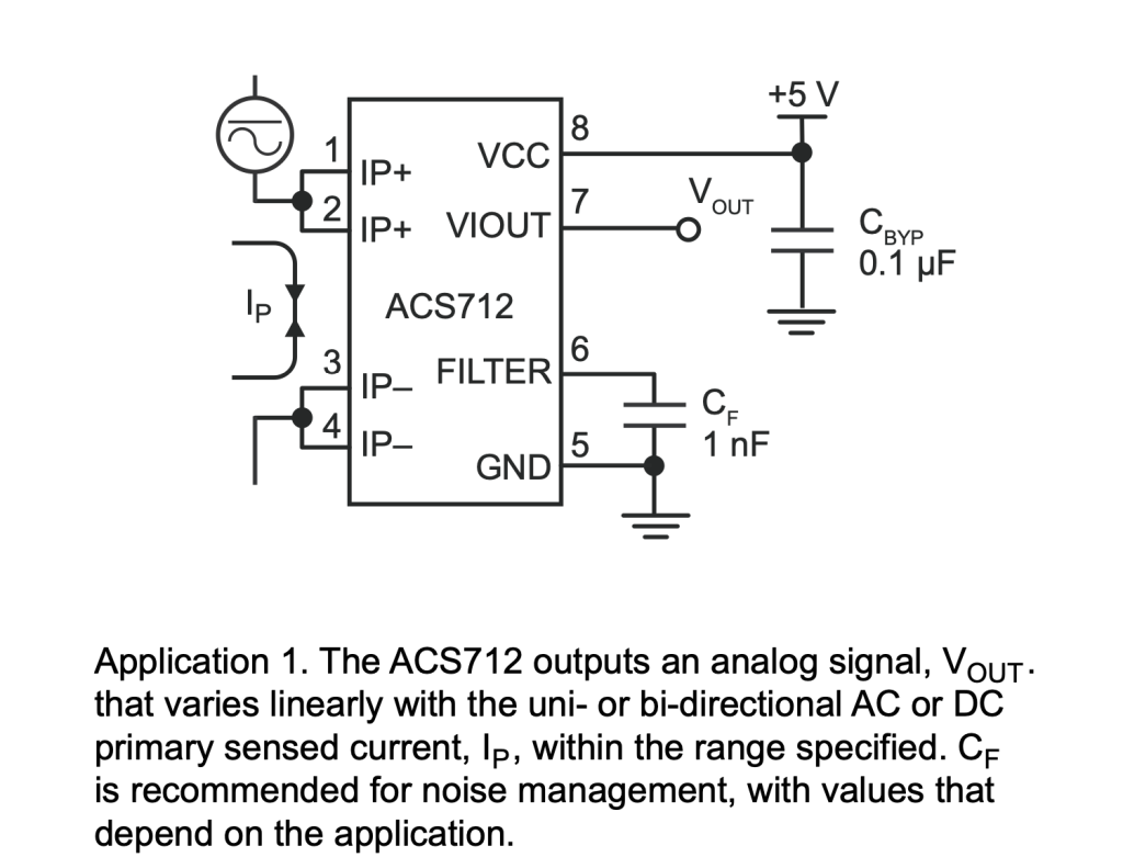
Typical Application:
Current ranges:
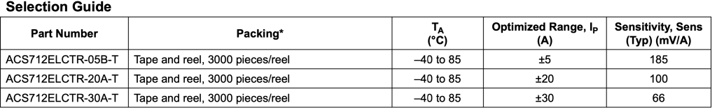
The one in this guide, 30A version is used.
2. Connection:
The connection of I2C LCD and ACS712 Current sensor module as following:
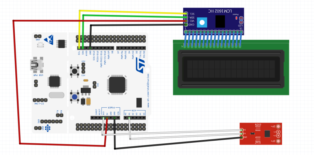
| ACS712 | STM32F4xx |
| Vcc | 3V3 |
| Vout | PA1 |
| GND | GND |
3. Driver development:
Since this guide uses ADC and I2C LCD:
For I2C LCD guide from here.
ADC Single channel single conversion from here.
Create new source and hear file wit name of acs712.c and acs712.h respectively.
Within acs712.h:
#ifndef ACS712_H_
#define ACS712_H_

#include "stdint.h"

void acs712_init();
int32_t get_acs712_current();


#endif /* ACS712_H_ */
The header file contains the stdint library and two function, asc712_init and get_acs712_current.
Within acs712.c we start off by including the main stm32f4xx header file:
#include "stm32f4xx.h"
also, include acs712.h header file:
#include "acs712.h"
Declare the following two variables:
uint16_t adc_data;

uint32_t current;
For initializing asc712, it is the same for single channel single conversion method:
void acs712_init()
{
	/*Enable floating point unit:  Enable CP10 and CP11 full access*/
	SCB->CPACR |=(1<<20);
	SCB->CPACR |=(1<<21);
	SCB->CPACR |=(1<<22);
	SCB->CPACR |=(1<<23);

	RCC->AHB1ENR|=RCC_AHB1ENR_GPIOAEN; //enable gpio a clock
	GPIOA->MODER|=GPIO_MODER_MODER1;  //set the PA1 to analog mode

	RCC->APB2ENR|=RCC_APB2ENR_ADC1EN; //enable adc clock

	ADC1->CR2=0; //disable the adc

	ADC1->SQR3|=1;

	ADC1->SMPR2|= (0x07<<ADC_SMPR2_SMP1_Pos);

	ADC1->CR2|=1; //enable the adc

}
Now, for getting the current function:
int32_t get_acs712_current()
{
	adc_data=0;
	for (int i=0;i<10;i++){
	ADC1->CR2|=ADC_CR2_SWSTART; //start adc conversion

	while(!((ADC1->SR)&ADC_SR_EOC)){;}

	adc_data+=ADC1->DR;
	}
	adc_data=adc_data/10;

	current=(18.85*adc_data)-38074;
	return current;

}
The process as following:
- Reset the adc_data to zero
- Accumulate the ADC values of 10 samples by starting the ADC, waiting for it to finish and and get the data.
- Divide the accumulated value by 10.
- Plug the value to the required equation.
- Return the value of the current.
The equation is based on taking adc value of 100mA steps up to 5A (Limited by my PSU) and get the average of 10 samples and using linear regression to get the equation.
For more information about linear regression, please check this article from wikipedia here.
3. Code:
You may download the code from here:
4. Results:
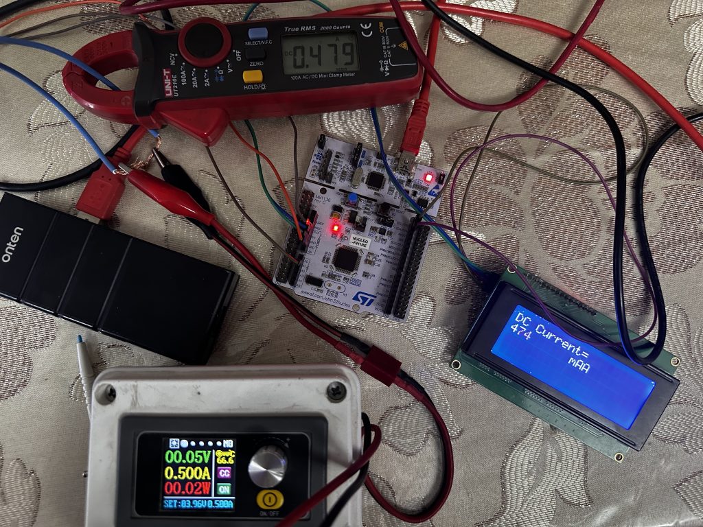
Happy coding 🙂
Add Comment