
In the previous guide (here), we took a look at the ADC in continuous mode with DMA. In that guide, we used the ADC to trigger freely. In this guide, we shall use timer to trigger the adc to convert the channel(s).
In this guide, we shall cover the following:
- ADC Configuration for timer trigger and DMA.
- Configure the DMA.
- Configure the timer.
- Code.
- Results.
1. Configuring the ADC for timer trigger and DMA:
In order to configure the ADC, we need to configure some bits in CR2:
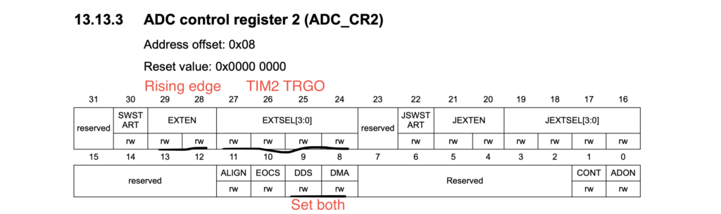
We need to set the following:
- EXTEN to rising edge.
- EXTSEL to be Timer 2 TRGO event
- DDS and DMA.
Hence the ADC configuration as following:
/*ADC related set up*/
	RCC->AHB1ENR		|=RCC_AHB1ENR_GPIOAEN;
	RCC->APB2ENR		|=RCC_APB2ENR_ADC1EN;
	GPIOA->MODER		|=GPIO_MODER_MODE0_0|GPIO_MODER_MODE0_1;
	ADC1->CR2			|=ADC_CR2_DMA|ADC_CR2_DDS;
	ADC1->CR2			|=ADC_CR2_EXTEN_0;
	ADC1->CR2			|=ADC_CR2_EXTSEL_1|ADC_CR2_EXTSEL_2;
Note: Don’t start the ADC yet.
2.Configure the DMA:
Before we configure the DMA, we need to check which channel and stream is needed:
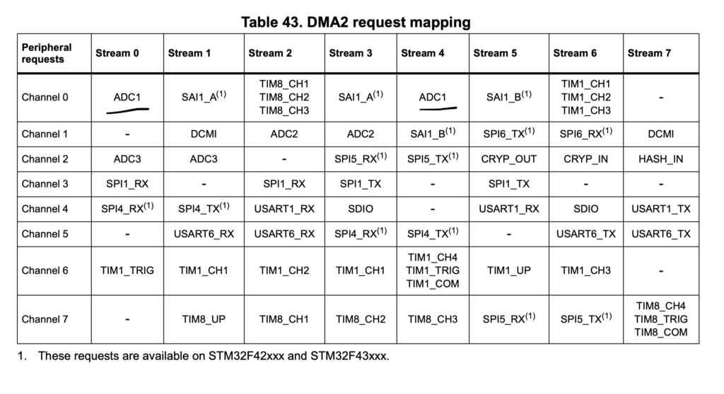
We have stream0 and stream4. In this guide, we shall use stream0.
In order to configure the DMA we need to set the following:
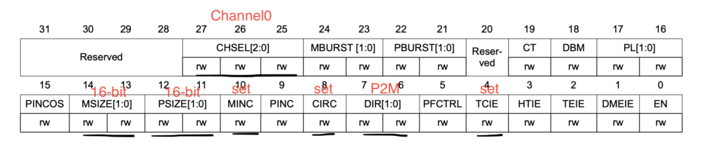
- Channel to 0.
- Memory and peripheral sizes to 16-bit (half-word).
- Set memory increment.
- Set the mode to be circular.
- Direction to be peripheral to memory.
- Transfer complete interrupt.
Hence the configuration code as following:
	RCC->AHB1ENR		|=RCC_AHB1ENR_DMA2EN;
	DMA2_Stream0->CR	&=~DMA_SxCR_EN;
	while(DMA2_Stream0->CR ==DMA_SxCR_EN){;}
	DMA2_Stream0->CR	|=DMA_SxCR_MSIZE_0|DMA_SxCR_PSIZE_0|DMA_SxCR_MINC|DMA_SxCR_TCIE|DMA_SxCR_CIRC;
	DMA2_Stream0->PAR	 =(uint32_t)(&(ADC1->DR));
	DMA2_Stream0->M0AR 	 =(uint32_t )(adc_data);
	DMA2_Stream0->NDTR	 =10;
	NVIC_EnableIRQ(DMA2_Stream0_IRQn);
3. Timer configuration:
Since we are using timer2, we need to configure to The update event is selected as trigger output (TRGO) as following:
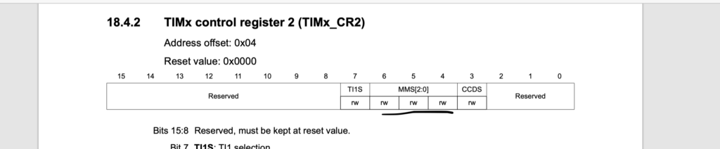
/* Timer related setup*/
	RCC->APB1ENR		|=RCC_APB1ENR_TIM2EN;
	TIM2->PSC			 =16000-1;
	TIM2->ARR			 =10-1;
	TIM2->CR2			|=TIM_CR2_MMS_1;
Finally, we launch the peripheral in this following order:
/*Launch the ADC*/
	ADC1->CR2			|=ADC_CR2_ADON;
	/*Launch the DMA*/
	DMA2_Stream0->CR 	|=DMA_SxCR_EN;
	/*Launch the timer*/
	TIM2->CR1			|=TIM_CR1_CEN;
In the main loop, we wait until the transfer in completed:
while(1)
	{
		if(finished==1)
			{
			finished=0;
			printf("adc values=\r\n");
			for (int i=0;i<10;i++)
				{
				printf("adc_data[%d]=%d\r\n",i,adc_data[i]);
				}
			printf("----------------------------\r\n");

			}


	}
Finally interrupt handler for the DMA as following:
void DMA2_Stream0_IRQHandler(void)
		{

		if(((DMA2->LISR)&DMA_LISR_TCIF0))
				{
				finished=1;
				DMA2->LIFCR=DMA_LIFCR_CTCIF0;
				}
		NVIC_ClearPendingIRQ(DMA2_Stream0_IRQn);
		}
Here, we are retargeting printf to be used with SWO (from here).
4. Code:
The entire code as following:
#include "stm32f4xx.h"                  // Device header
#include "stdio.h"
uint16_t adc_data[10];
volatile uint8_t finished=0;
int main(void)
{
	/*ADC related set up*/
	RCC->AHB1ENR		|=RCC_AHB1ENR_GPIOAEN;
	RCC->APB2ENR		|=RCC_APB2ENR_ADC1EN;
	GPIOA->MODER		|=GPIO_MODER_MODE0_0|GPIO_MODER_MODE0_1;
	ADC1->CR2			|=ADC_CR2_DMA|ADC_CR2_DDS;
	ADC1->CR2			|=ADC_CR2_EXTEN_0;
	ADC1->CR2			|=ADC_CR2_EXTSEL_1|ADC_CR2_EXTSEL_2;

	/*DMA related setup*/
	RCC->AHB1ENR		|=RCC_AHB1ENR_DMA2EN;
	DMA2_Stream0->CR	&=~DMA_SxCR_EN;
	while(DMA2_Stream0->CR ==DMA_SxCR_EN){;}
	DMA2_Stream0->CR	|=DMA_SxCR_MSIZE_0|DMA_SxCR_PSIZE_0|DMA_SxCR_MINC|DMA_SxCR_TCIE|DMA_SxCR_CIRC;
	DMA2_Stream0->PAR	 =(uint32_t)(&(ADC1->DR));
	DMA2_Stream0->M0AR 	 =(uint32_t )(adc_data);
	DMA2_Stream0->NDTR	 =10;
	NVIC_EnableIRQ(DMA2_Stream0_IRQn);

	/* Timer related setup*/
	RCC->APB1ENR		|=RCC_APB1ENR_TIM2EN;
	TIM2->PSC			 =16000-1;
	TIM2->ARR			 =10-1;
	TIM2->CR2			|=TIM_CR2_MMS_1;
	/*Launch the ADC*/
	ADC1->CR2			|=ADC_CR2_ADON;
	/*Launch the DMA*/
	DMA2_Stream0->CR 	|=DMA_SxCR_EN;
	/*Launch the timer*/
	TIM2->CR1			|=TIM_CR1_CEN;

while(1)
	{
		if(finished==1)
			{
			finished=0;
			printf("adc values=\r\n");
			for (int i=0;i<10;i++)
				{
				printf("adc_data[%d]=%d\r\n",i,adc_data[i]);
				}
			printf("----------------------------\r\n");

			}
	}

}


void DMA2_Stream0_IRQHandler(void)
		{

		if(((DMA2->LISR)&DMA_LISR_TCIF0))
				{
				finished=1;
				DMA2->LIFCR=DMA_LIFCR_CTCIF0;
				}
		NVIC_ClearPendingIRQ(DMA2_Stream0_IRQn);
		}

int __io_putchar(int ch)
	{
	 ITM_SendChar(ch);
	return ch;
	}
5. Result:
When you run the code and open new Serial Wire Viewer window, you should get the following results:
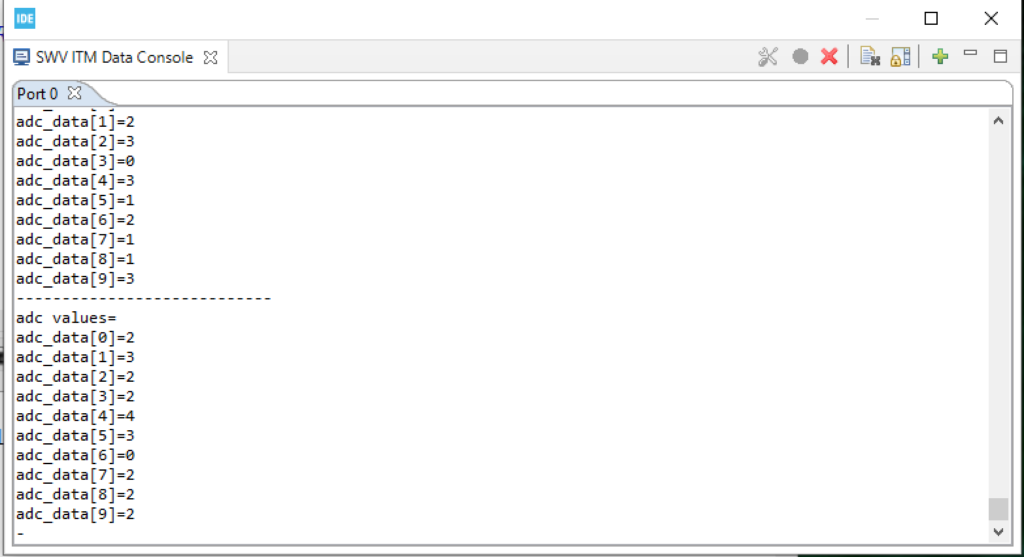
Happy coding 🙂
Add Comment