
In the previous guide (here), we took a look how to configure the SPI module on STM32F103 and successfully transmit data over the SPI bus. Now, we shall receive data from the SPI bus.
In this guide, we shall cover the following:
- Receive data sequence.
- Receive data.
- Receiver test.
- Code.
- Results.
1. Receive data sequence:
In order to receive data from the SPI bus, when data transfer is complete:
• The data in the shift register is transferred to the RX Buffer and the RXNE flag is set
• An interrupt is generated if the RXNEIE bit is set in the SPI_CR2 register.
Hence, the sequence as following:
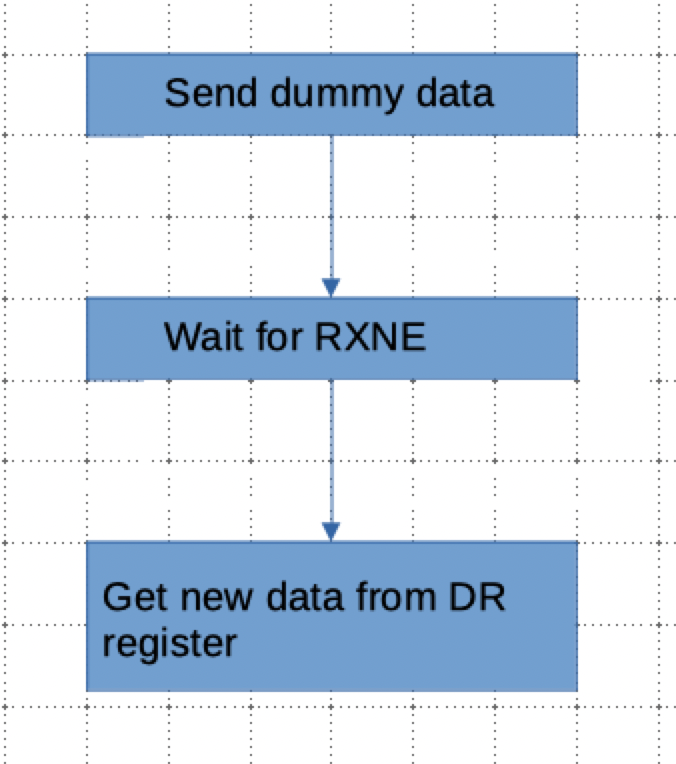
Now, we shall do the code for receiving data.
2. Receive data:
From the previous guide, open the spi.h header file and add the following function:
void spi_receive(uint8_t *data,uint32_t size);
Thats all for the header file.
Within spi.c file, declare the function as following:
void spi_receive(uint8_t *data,uint32_t size)
The function takes two arguments:
- Pointer to the data to be read.
- Size of the data to be read.
Since the function take size as argument, we shall iterate the size variable in the while loop as following:
while(size)
	{
Within the while size, we shall do the following:
First send dummy data:
/*Send dummy data*/
SPI1->DR =0;
For for RXNE to be set from the status register:
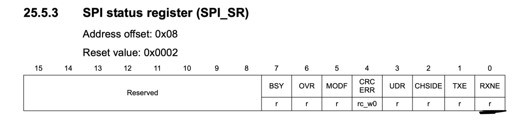
/*Wait for RXNE flag to be set*/
while(!(SPI1->SR & (SPI_SR_RXNE))){}
Read the DR register and increment the pointer:
/*Read data from data register*/
*data++ = (SPI1->DR);
Decrement the size variable:
size--;
close both brackets for while loop and the function.
Hence, the function as following:
void spi_receive(uint8_t *data,uint32_t size)
{

	while(size)
	{
		/*Send dummy data*/
		SPI1->DR =0;

		/*Wait for RXNE flag to be set*/
		while(!(SPI1->SR & (SPI_SR_RXNE))){}

		/*Read data from data register*/
		*data++ = (SPI1->DR);
		size--;
	}
}
3. Receiver test:
To test the receiver, we shall use MPU9250 in SPI mode to test the functionality of both, TX and RX function at the same time.
The connection of MPU9250 with STM32F103 as following:
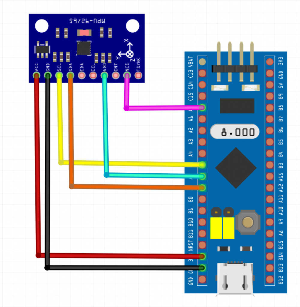
| MPU9250 | STM32F103 |
| Vcc | 3V3 |
| GND | GND |
| SCL | PA5 |
| SDA | PA7 |
| AD0 | PA6 |
| NCS | PA0 |
You can download the code from code section.
4. Code:
You may download the full code from here:
5. Results:
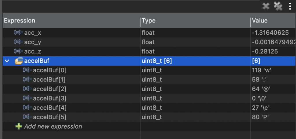
Upload the code to your MCU and open debugging session and within live expression, add the following variables:
acc_x
acc_y
acc_z
Run the code and you should get the following:
Happy coding 🙂
2 Comments
Thank you for the tutorial for SPI on stm32f103 , the information presented here is so helpful. Keep it up! However, I don,t understand this line : *data++ = (SPI1->DR);
Why combining a pointer(*) with incremment(++), could you explain further please?
Since the function accept pointers to hold the read values from the SPI. Since we are pointing to an array, the pointer will point to the first element of the array, hence we are incrementing the pointer to point to the next element.
You could use data[i].
Add Comment