
In the previous guide (here), we took a look at GPIO output using STM32L053, now we shall see how to develop GPIO input driver.
In this guide, we shall cover the following:
- Input modes.
- Develop the GPIO input driver.
- Code to toggle the LED using push-button.
- Code.
- Demo.
1. Input modes:
GPIO input modes include
- high impedance
- pull-up
- pull-down
Floating, High Impedance, Tri-Stated
Floating, high impedance, and tri-stated are three terms that mean the same thing: the pin is just flopping in the breeze. Its state is indeterminate unless it is driven high or low externally. You only want to configure a pin as floating if you know it will be driven externally. Otherwise, configure the input using pulling resistors.
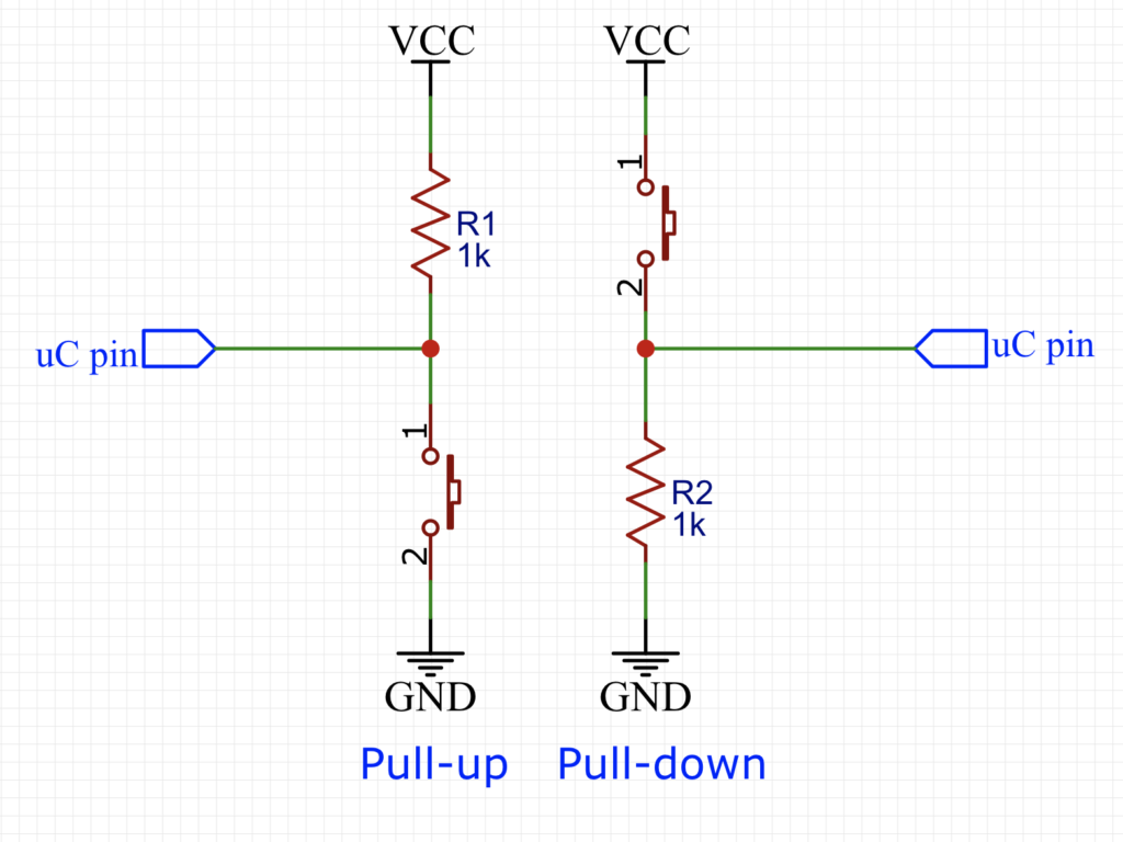
Pull Up/Down
If an input is configured with an internal pull-up, it will be high unless it is externally driven low. Pull-down inputs do the opposite ( they’re low unless driven high).
2.Develop GPIO input driver:
Before we start developing the GPIO input driver, we need to figure out which pin is the push-button of Nucleo-64 is connected to.
According to the user manual of the STM32 Nucleo-64, the push-button is connected to pin PC13.
Hence, we start off by enabling clock access to GPIOC as following:
	/*Enable clock access to GPIOC*/
	RCC->IOPENR |= RCC_IOPENR_GPIOCEN;
Then configure the pin as input by reseting bit 26-27 of MODER register as following:
GPIOC->MODER&=~ GPIO_MODER_MODE13;
In order to read the GPIO state, we can use GPIOC->IDR as following:
GPIOC->IDR&GPIO_IDR_ID13
This will return either 1 if the button is not pressed and 0 if the button is pressed.
3. Code to toggle the LED using push-button:
To make the guide interesting, we shall toggle the LED with each press of the push button.
We start by enabling clock access to GPIOA and set PA5 as output:
	/*Enable clock access to GPIOA*/
	RCC->IOPENR |= RCC_IOPENR_GPIOAEN;
	/*Set PA5 as output pin*/
	GPIOA->MODER |= GPIO_MODER_MODE5_0;
	GPIOA->MODER  &=~GPIO_MODER_MODE5_1;
Then we need a variable to hold the state:
uint8_t state;
in while (1) loop:
First we check if the button is pressed and the state is 0 as following:
if ((GPIOC->IDR&GPIO_IDR_ID13)==0&&(state==0))
If the button is pressed and state is 0, perform the following:
- Set state to 1.
- Turn on LED.
- Wait until the button is released.
			{
			state=1;
			GPIOA->BSRR=GPIO_BSRR_BS_5;
			while((GPIOC->IDR & GPIO_IDR_ID13)==0);
			}
Then we check if the button is pressed and the state is 1, if the conditions are met, perform the following:
- Set state to 0.
- Turn off the LED.
- wait until the button is released.
	if ((GPIOC->IDR & GPIO_IDR_ID13)==0&&(state==1))
			{
			state=0;
			GPIOA->BSRR=GPIO_BSRR_BR_5;
			while((GPIOC->IDR & GPIO_IDR_ID13)==0);
			}
4. Code:
The entire code as following:
#include  "stm32l0xx.h"

uint8_t state;


int main(void)
{
	/*Enable clock access to GPIOA*/
	RCC->IOPENR |= RCC_IOPENR_GPIOAEN;
	/*Enable clock access to GPIOC*/
	RCC->IOPENR |= RCC_IOPENR_GPIOCEN;

	/*Set PA5 as output pin*/
	GPIOA->MODER |= GPIO_MODER_MODE5_0;
	GPIOA->MODER  &=~GPIO_MODER_MODE5_1;
	/* Set PC13 as input*/
	GPIOC->MODER&=~ GPIO_MODER_MODE13;

	while(1)
	{
		if ((GPIOC->IDR&GPIO_IDR_ID13)==0&&(state==0))
			{
			state=1;
			GPIOA->BSRR=GPIO_BSRR_BS_5;
			while((GPIOC->IDR & GPIO_IDR_ID13)==0);
			}

		if ((GPIOC->IDR & GPIO_IDR_ID13)==0&&(state==1))
			{
			state=0;
			GPIOA->BSRR=GPIO_BSRR_BR_5;
			while((GPIOC->IDR & GPIO_IDR_ID13)==0);
			}

	}

}
5. Demo:
Happy coding 🙂
Add Comment