
In this new getting started with STM32L0, we shall use STM32L053 Nucleo-64 and blink onboard LED using only registers and develop the firmware from scratch without using Hardware Abstraction Layer or Low Level (LL).
In this guide, we shall cover the following:
- Getting the documents.
- Developing bare metal GPIO output.
- Demo.
1. Getting the documents:
In this guide and the upcoming guides, will need the following three documents
- STM32L053 Datasheet.
- STM32L053 Reference Manual.
- Nucleo-64 User Manual.
You can find the links for the mentioned documents :
STM32L053 datasheet (here).
STM32L053 Reference Manual (here).
Nucleo-64 User Manual (here).
Since the guide uses STM32CubeIDE, it requires extra steps. However, you don’t need to think about since everything will be attached at the end of the guide.
2. Developing Bare Metal GPIO driver:
First step is to find which pin of our Nucleo the LED is connected to:
Referring to STM32 Nucleo-64 User manual, we can find that the LED is connected to PA5.
After we figured out to which pin is the LED connected to, we can start developing the code.
We start off by including the chip header file as following:
#include "stm32l0xx.h"
Then, we need to enable clock access to GPIOA.
In order to enable clock access to the GPIOA, we need to go to reference manual and check the register named GPIO clock enable register.
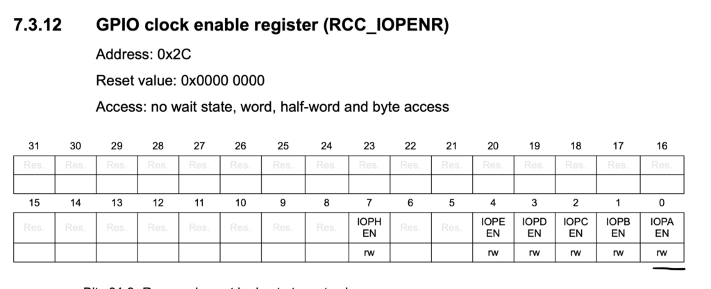
	/*Enable clock access to GPIOA*/
	RCC->IOPENR |= RCC_IOPENR_GPIOAEN;
After the clock we need to set PA5 as output, to set it as output, open section GPIO port mode register.
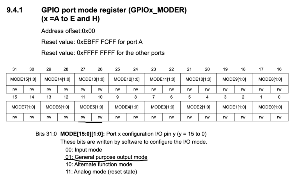
Since the reset state of the pin as analog mode, we need to set bit10 and reset bit11 as following:
	/*Set PA5 as output pin*/
	GPIOA->MODER |= GPIO_MODER_MODE5_0;
	GPIOA->MODER  &=~GPIO_MODER_MODE5_1;
Now we can toggle the LED on-0ff as following:
In GPIO port output data register, set bit 5 which correspond to pin5 as following:
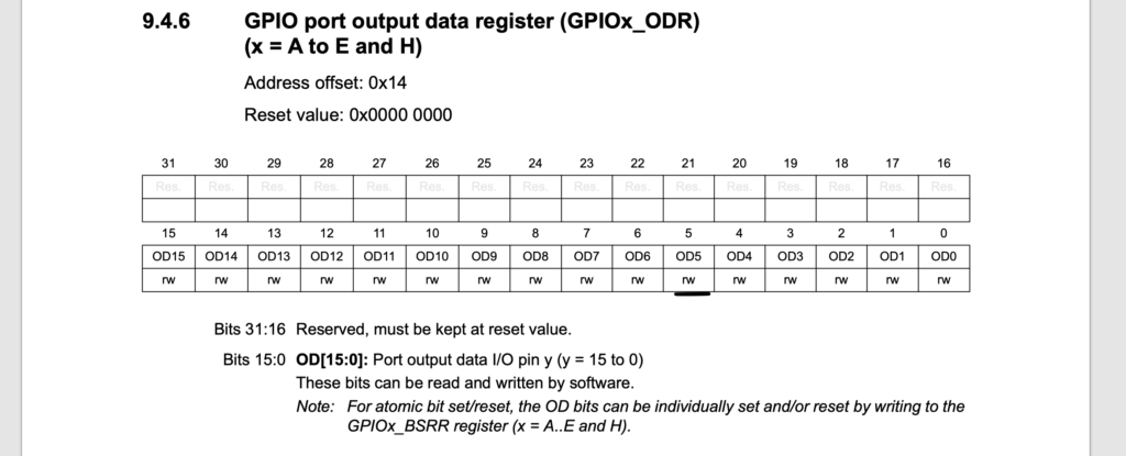
GPIOA->ODR |= GPIO_ODR_OD5;
delay a little bit as following:
for(int i=0;i<10000;i++);
Reset bit5 of ODR as following:
GPIOA->ODR &=~ GPIO_ODR_OD5;
delay once more:
for(int i=0;i<100000;i++);
Hence, the entire code as following:
#include  "stm32l0xx.h"


int main(void)
{
	/*Enable clock access to GPIOA*/
	RCC->IOPENR |= RCC_IOPENR_GPIOAEN;


	/*Set PA5 as output pin*/
	GPIOA->MODER |= GPIO_MODER_MODE5_0;
	GPIOA->MODER  &=~GPIO_MODER_MODE5_1;

	while(1)
	{

		GPIOA->ODR |= GPIO_ODR_OD5;
		for(int i=0;i<100000;i++);
		GPIOA->ODR &=~ GPIO_ODR_OD5;
		for(int i=0;i<100000;i++);

	}

}
You may download the project included the required header file from here:
3. Demo:
Happy coding 🙂
Add Comment