
In the pervious guide (here), we took a look how to configure the timer in encoder mode to read the pulses generated by the encoder.
In this guide we cover the following:
- What is output compare mode
- Required parts
- Code
- Demo
1. What is output compare mode:
In this mode, the timer shall count to the maximum level (set by the ARR), the following will happen:
- Assigns the corresponding output pin to a programmable value defined by the output compare mode.
- Sets a flag in the interrupt status register.
- Generates an interrupt if the corresponding interrupt mask is set.
- Sends a DMA request if the corresponding enable bit is set.
In our case, we will toggle PA5 (TIM2_CH1) based on out setting.
2. Required parts:
In this guide, we need only the Nucleo board, in this case STM32F446RE-Nucleo-64. Since the build LED is connected to PA5 which is channel 1 of timer 2
3. Code:
We start off by enabling clock access to GPIOA:
RCC->AHB1ENR |= RCC_AHB1ENR_GPIOAEN;
Then set PA5 to alternate function:
GPIOA->MODER	|=	GPIO_MODER_MODE5_1;
GPIOA->MODER	&= ~GPIO_MODER_MODE5_0;
Then we set the type of alternate function:
#define TIM2_AF 0x01
GPIOA->AFR[0] |= (TIM2_AF<<20);
Then we enable clock access to the timer2:
RCC->APB1ENR |= RCC_APB1ENR_TIM2EN;
Disable the timer:
TIM2->CR1 &=~ TIM_CR1_CEN;
In order to toggle the pin when a match we need to set OC1M bits in CCMR1 to toggle on match
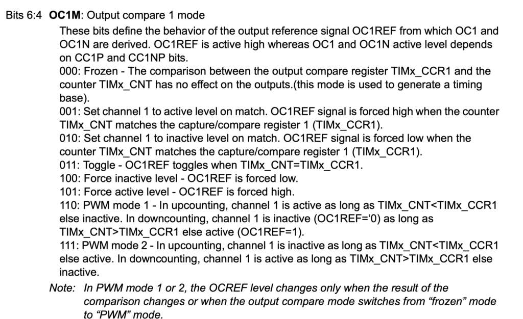
From the image, we can set this mode when both bit4 and bit5 are set, hence we can set them as following:
TIM2->CCMR1|=TIM_CCMR1_OC1M_0|TIM_CCMR1_OC1M_1;
We enable the channel as following:
TIM2->CCER|=TIM_CCER_CC1E;
We set the prescaler and period to get 1 second as following:
TIM2->PSC=16000-1; /*16 000 000 / 16 000 =1 000*/
TIM2->ARR=1000-1; /*1 000 / 1 000 = 1HZ*/
Finally, we enable the timer as following:
TIM2->CR1 |= TIM_CR1_CEN;
Hence, the entire code as following:
#include "stm32f4xx.h"                  // Device header

int main(void)
	{
	#define TIM2_AF 0x01
	RCC->AHB1ENR	|=	RCC_AHB1ENR_GPIOAEN;
	GPIOA->MODER	|=	GPIO_MODER_MODE5_1;
	GPIOA->MODER	&= ~GPIO_MODER_MODE5_0;
	GPIOA->AFR[0] |= (TIM2_AF<<20);

	RCC->APB1ENR  |=  RCC_APB1ENR_TIM2EN;
	TIM2->CR1     &=~ TIM_CR1_CEN;
	TIM2->CCMR1|=TIM_CCMR1_OC1M_0|TIM_CCMR1_OC1M_1;
	TIM2->CCER|=TIM_CCER_CC1E;
	TIM2->PSC=16000-1; /*16 000 000 / 16 000 =1 000*/
	TIM2->ARR=1000-1; /*1 000 / 1 000 = 1HZ*/
	TIM2->CR1     |= TIM_CR1_CEN;

	while(1);
	}
As you noticed, the while one loop is empty since the toggling process is done by hardware level not software
2 Comments
GPIO -> AFR [0 ] | = (TIM2_AF << 20);
What are the 20 elements of the array?
oc1m=011, right?
This means bit 2 of the register not the array element.
For array, we use [position].
Add Comment