
Embeetle IDE is a lightweight and efficient development environment designed for embedded systems, offering a streamlined workflow for various microcontrollers, including STM32. This guide will walk you through the process of importing a custom STM32 project into Embeetle IDE, ensuring a smooth setup and integration.
In this guide, we shall cover the following:
- STM32CubeMX Generation.
- Embeetle IDE.
- Testing the IDE.
- Results.
1. STM32CubeMX Generation:
First, we need to stat with STM32CubeMX to generate the code. To download STM32CubeMX, please visit this website here.
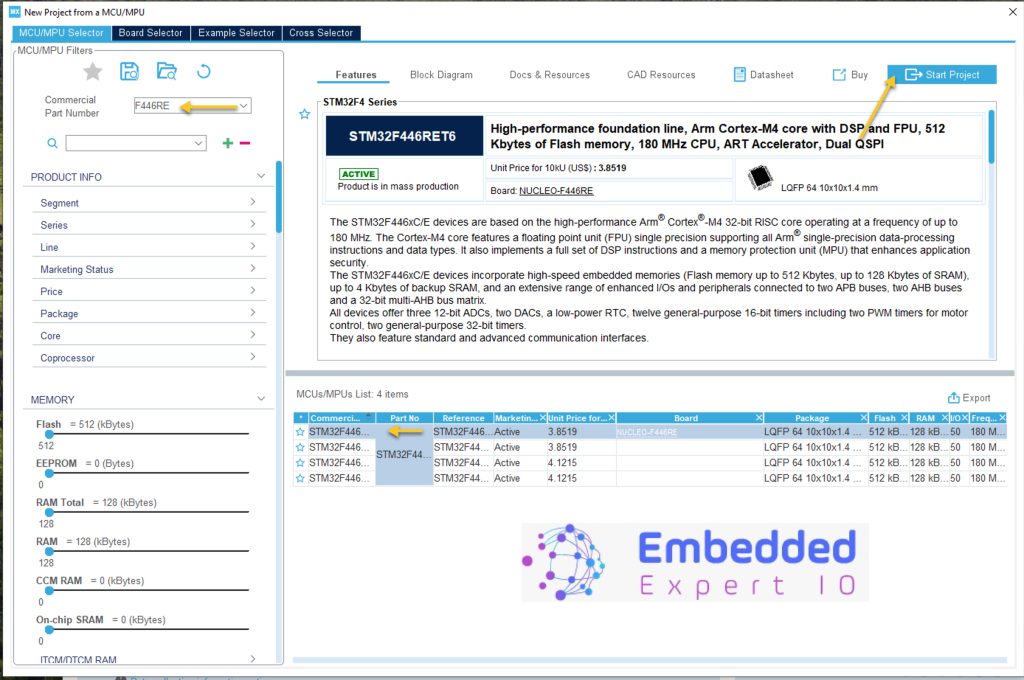
After launching STM32CubeMX, start a new project as following:

Next, select your STM32 MCU, (Here I am using STM32F446RE) as following and click on start project as following:
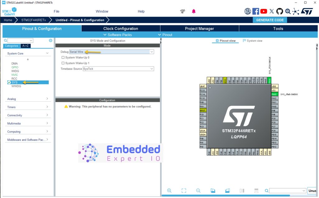
Next, from System core, select SYS and Set Debug to Serial Wire. This will set PA13 and PA14 as SWDIO and SWCLK respectively.
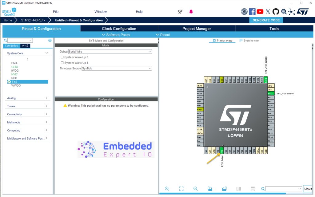
Next, set PA5 as output as following:
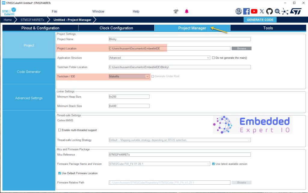
Next from Project Manager, give the project a name, set the desired destination and set IDE/toolchain to Make as following:
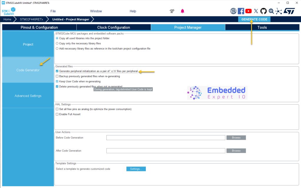
From Code Generation in Project Manager tab, enable generate peripheral initialization as pair of .c/.h files per peripheral and click on Generate code as following:
Thats all for STM32CubeMX section.
2. Embeetle IDE:
Before heading into how to use Embeetle IDE, please refer to this guide for how to download and install the IDE.
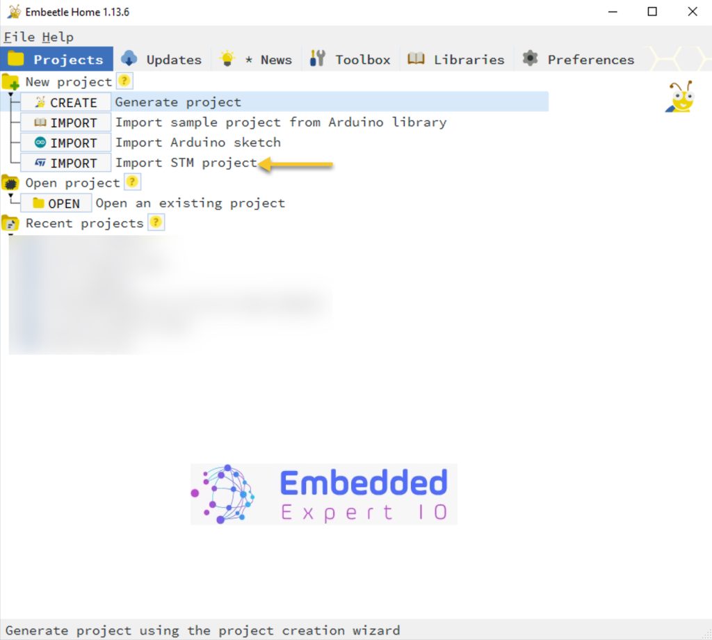
After the launch of Embeetle IDE, select import STM Project as following:
Next, select your STM32 project generate by STM32CubeMX:
- Select Keep or Replace.
- Select where to save Embeetle IDE project
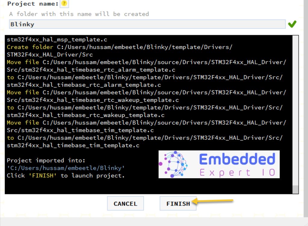
- Give Embeetle IDE project a name (blinky).
- Click on Next.
After while, finish will appear and click on it as following:
Next, a window will appear. Open main.c as following:
In user code begin 3, add the following two lines of code:
HAL_GPIO_TogglePin(GPIOA,GPIO_PIN_5);
HAL_Delay(1000);
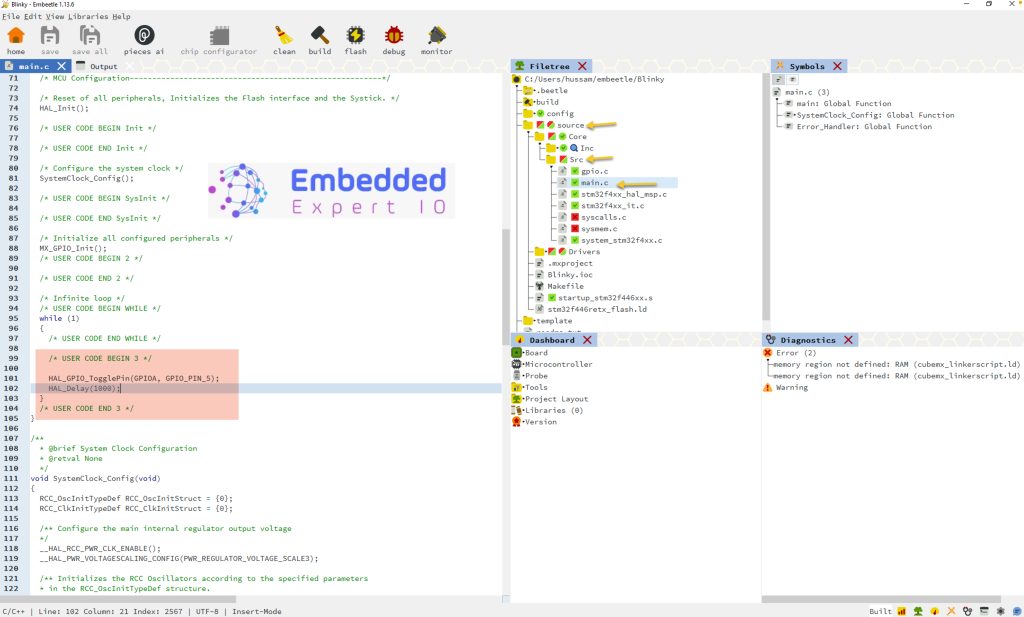
This code will turn on/off the LED each 1 second.
Next, click on build and then flash once the build is completed as following:

The code should be flashed on your MCU at this point and you should see the LED(LD2) on STM32F446RE Nucleo-64.
3. Results:
Happy coding 😉
Add Comment