In this guide on Micropython on STM32F411RE Nucleo-64, we shall see how to develop PWM driver to control various systems like LEDs DC motors etc.
In this guide, we shall cover the following:
- What is PWM.
- Micropython Driver.
- Hardware connection
- Results.
1. What is PWM:
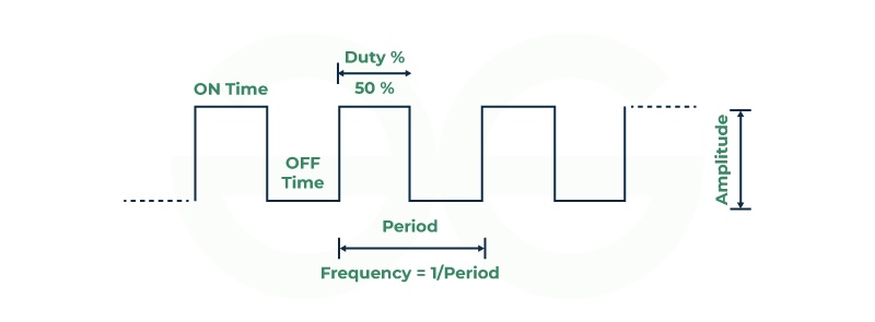
Pulse-width modulation (PWM), also known as pulse-duration modulation (PDM) or pulse-length modulation (PLM), is a technique used to represent a signal as a rectangular wave with a varying duty cycle (and sometimes a varying period). Let’s break it down:
- Duty Cycle: The duty cycle refers to the ratio of the time the signal is “on” (high) to the total time of one complete cycle. It is expressed as a percentage. For example, if a signal is on for 60% of the time and off for 40%, the duty cycle is 60%.
- Average Power Control: PWM is particularly useful for controlling the average power or amplitude delivered by an electrical signal. By switching the supply between 0% and 100% at a rate faster than the load can respond, we can effectively control the average power delivered to the load.
- Applications:
- Motor Control: PWM is commonly used to control motors (such as in fans, pumps, and robotics) because motors are not easily affected by discrete switching.
- Solar Panels: It’s a key method for controlling the output of solar panels to match battery requirements.
- Digital Controls: PWM works well with digital controls, allowing precise duty cycle adjustments.
- Communication Systems: In some cases, PWM duty cycles have been used to convey information over communication channels.
- Switching Frequency: The switching frequency (how often the signal switches on and off) varies depending on the application. It can range from several times a minute (e.g., electric stoves) to tens or hundreds of kilohertz (e.g., audio amplifiers).
- Advantages:
- Low power loss in switching devices (almost zero current when off).
- Works well with digital control systems.
- Used in various applications due to its flexibility.
- Disadvantages:
- Choosing the right switching frequency is crucial for smooth control.
- Too high a frequency can stress mechanical components.
- Too low a frequency can cause load oscillations.
In summary, PWM allows precise control of average power delivery by rapidly switching the signal on and off.
2. Micropython Driver:
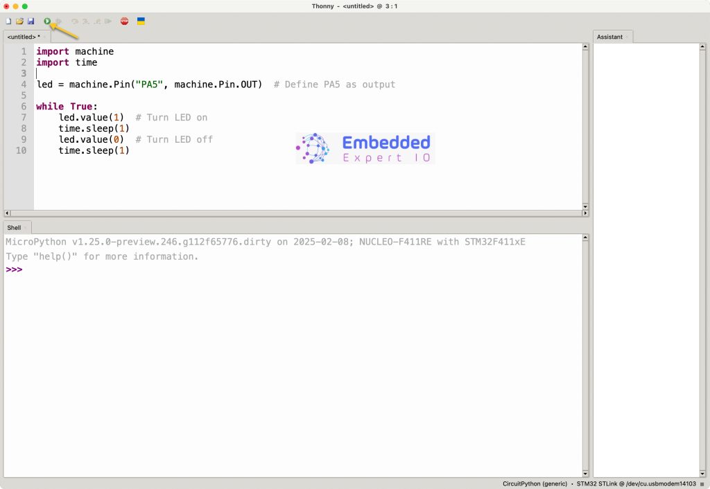
First, we need to configure Thonny to work with STM32F411 Nucleo-64. Please refer to this guide for how to install and configure Thonny.
First, we need to find which pins are connected to TIM2. From the datasheet of the STM32F411RE, we can find that PA0 to PA3 are connected to TIM2_CH1 to TIM2_CH4 respectively.
However, PA2 and PA4 are used for UART for micropython core. Hence, they can’t be used in out firmware.
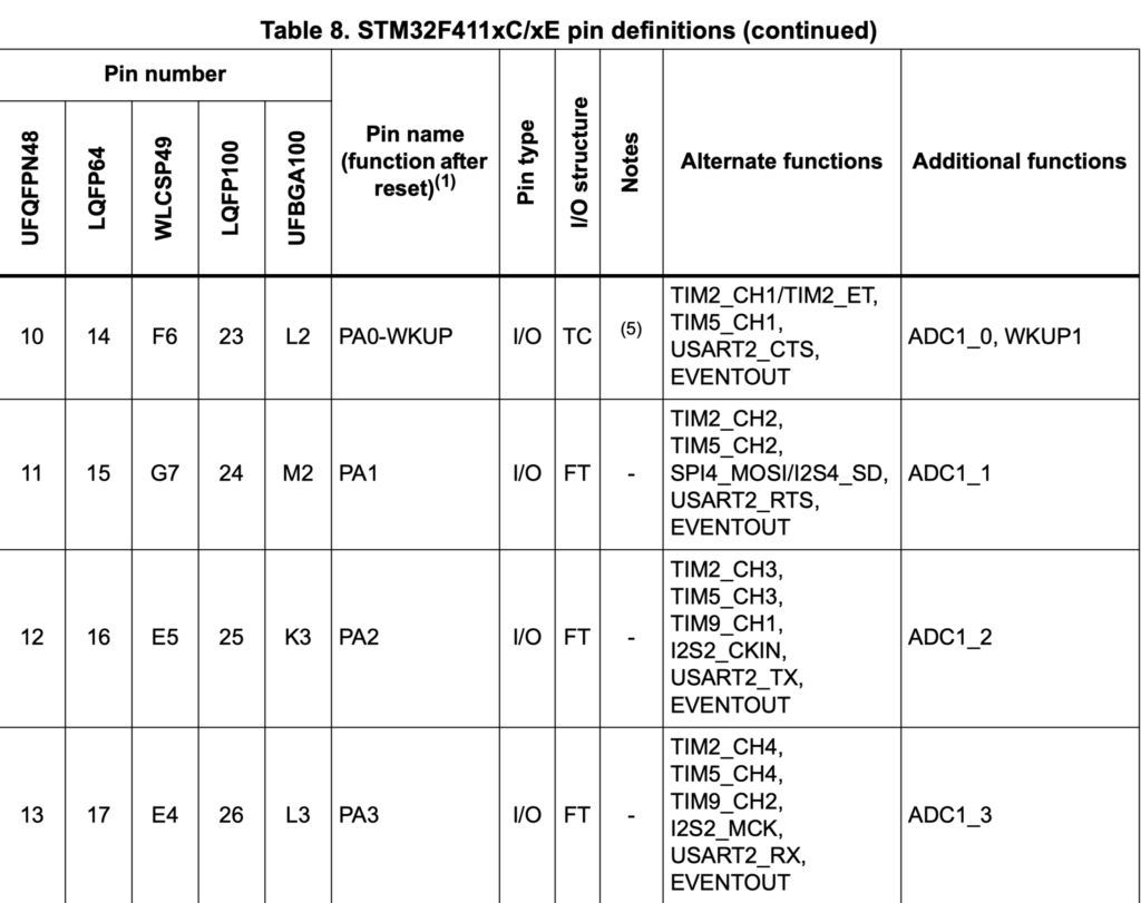
After finding which pins are connected to TIM2, we shall use PA0 as our PWM pin.
We start by importing pyb (pyboard) as following:
import pyb
Also, time to handle the delays as following:
import time
Next, we shall configure timer2 as following:
timer2 = pyb.Timer(2, freq=1000) # Set Timer 2 at 1 kHz
pyb.Timer shall configure timer2 with frequency of 1KHz. and store the object to configure TIM2 parameters.
Next, we shall configure the pin for PWM which can be achieved as following:
ch1 = timer2.channel(1, pyb.Timer.PWM, pin=pyb.Pin.board.PA0, pulse_width_percent=0)
The function shall take the following parameters:
- Time channel.
- Timer output type which is PWM in this case.
- Pin to be used which is PA0.
- Duty cycle (pulse width modulation percent), initially, it is zero.
Next, in while true loop:
while True:
  # Fade in
  for duty in range(0, 101, 2):  # 0% to 100% duty cycle
    ch1.pulse_width_percent(duty)
    time.sleep(0.02)  # Small delay for smooth transition

          # Fade out
  for duty in range(100, -1, -2):  # 100% to 0% duty cycle
    ch1.pulse_width_percent(duty)
    time.sleep(0.02)
The function:
ch1.pulse_width_percent(duty)
will set the percentage of the duty cycle of the PWM signal.
This will vary the duty cycle according to the for loop.
Thats all for the driver.
Click on run as following:
3. Hardware Connection:
The connection as following:

Since PA0 is connected to A0 pin of the arduino pins. Hence, we shall connect our LED to this pin.
Don’t forger to add 220Ohm to limit the current.
4. Results:
Happy coding 😉
2 Comments
Nice tutor, I am installing micropython.
You are welcome
Add Comment