A single microprocessor can serve several devices. There are two ways to do that: interrupts or polling. In the interrupt method, whenever any device needs service, the device notifies the CPU by sending it an interrupt signal. Upon receiving an interrupt signal, the CPU interrupts whatever it is doing and serves the device. The program associated with the interrupt is called the interrupt service routine (ISR) or interrupt handler. In polling, the CPU continuously monitors the status of a given device; when the status condition is met, it performs the service. After that, it moves on to monitor the next device until each one is serviced. Polling if often characterized by things if conditions.
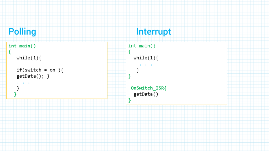
Although polling can monitor the status of several devices and serve each of them as certain conditions are met, it is not an efficient use of the CPU time. The polling method wastes much of the CPU’s time by polling devices that do not need service. So in order to avoid tying down the CPU, interrupts are used.
For instance, in a Timer we might wait until a determined amount of time elapses, and while waiting we cannot do anything else. That is a waste of the CPU’s time that could have been used to perform some useful tasks. On the other and if we use the interrupt method, the CPU can go about doing other tasks, and when the COUNT flag is raised the Timer will interrupt the CPU to let it know that the time is elapsed.
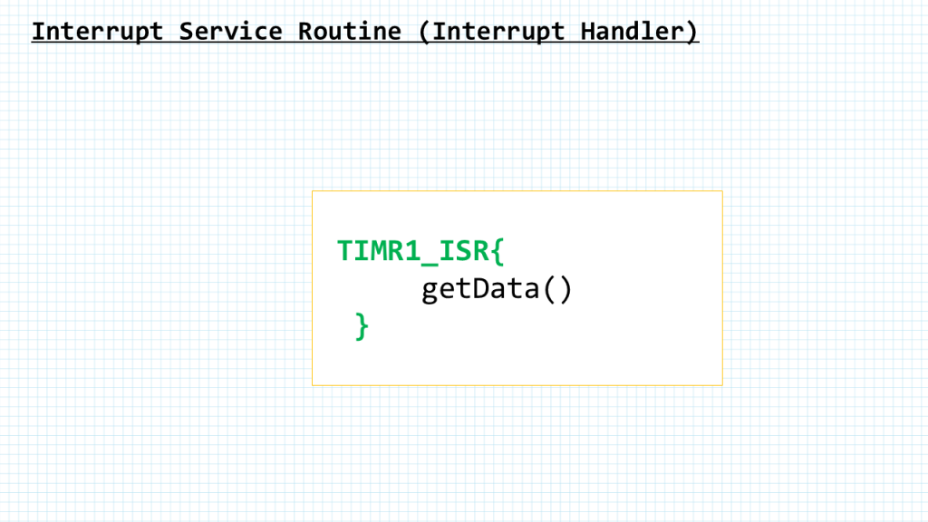
For every interrupt there must be a program associated with it. When an interrupt occurs this program is executed to perform certain service for the interrupt. This program is commonly referred to as an interrupt service routine (ISR). The interrupt service routine is also called the interrupt handler. When an interrupt occurs, the CPU runs the interrupt service routine.
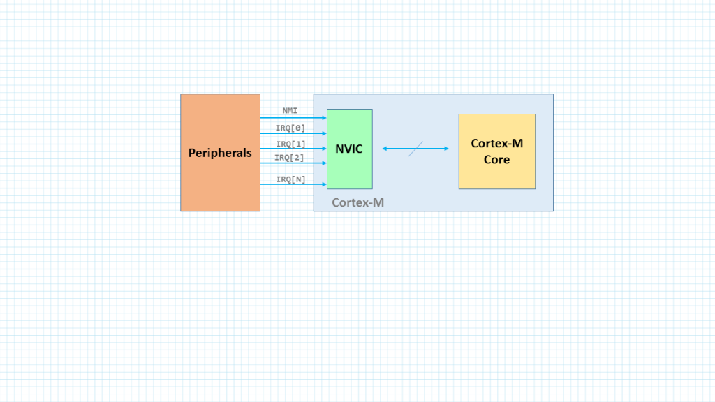
As we can see in this arrangement, in the ARM processor there are pins that are associated with hardware interrupts. They are input signals into the CPU. When the signals are triggered, CPU pushes the the program counter register (or PC) onto the stack and loads the PC register with the address of the interrupt service routine. This causes the ISR to get executed.
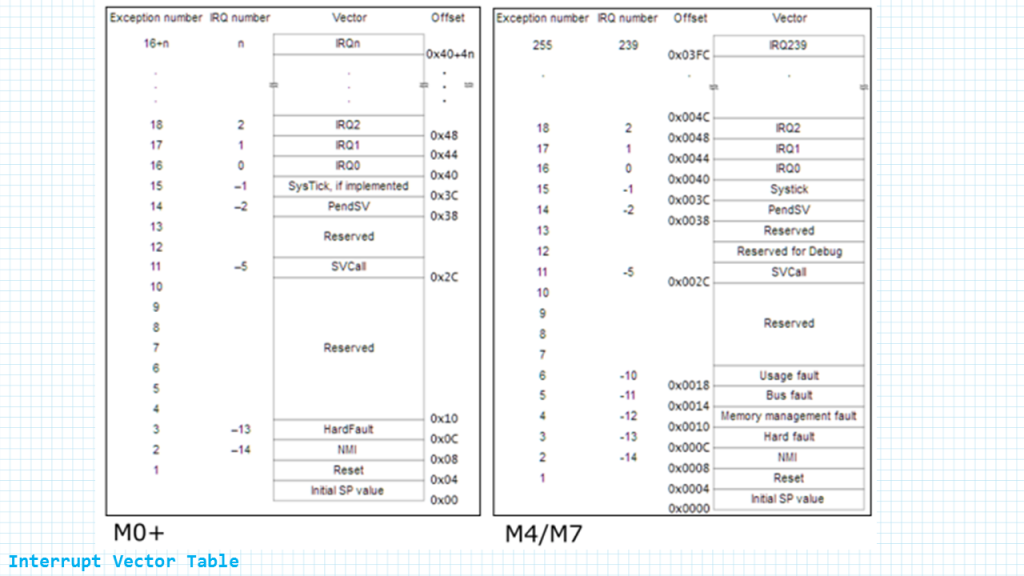
This table here shows what is known as the interrupt vector.
This table is taken from the ARM Generic user Guide we can find them in any arm microcontroller datasheet as well. The first column here says the Exception number, the next column says the interrupt number the third column says the offset and the fourth column says vector. You can think of the vector as the name of the interrupt.
As we call tell from the offset, for every interrupt there are four bytes of memory allocated in the interrupt vector table. These four memory locations provide the addresses of the interrupt service routine for which the interrupt was invoked.
Since there is a program (or piece of code which we call the Interrupt Service Routine) associated with every interrupt and this program resides in memory, there must be a look-up table to hold the addresses of these ISRs. This look-up table is called interrupt vector table. In the ARM, the lowest 1024 bytes (256 × 4 = 1024) of memory space are set aside for the interrupt vector table and must not be used for any other function.
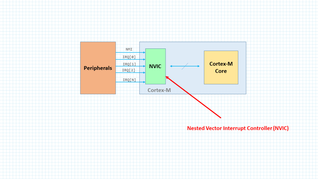
The NVIC of the ARM Cortex-M has room for the total of 255 interrupts and exceptions.The NVIC in ARM Cortex-M assigns the first 15 interrupts for internal use.
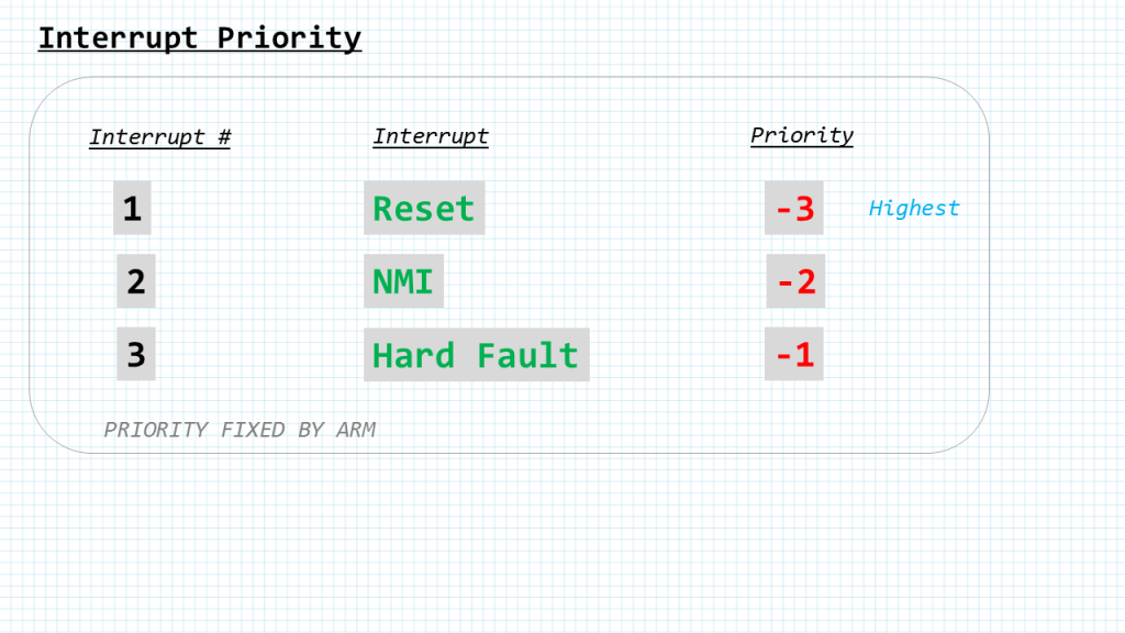
In the ARM Cortex-M the Reset, NMI and Hard Fault exceptions have fixed priority levels and are set by the ARM itself and not subject to change. Among the Reset, NMI and Hard Fault, the Reset has the highest priority.
For instance, If both NMI and and a different interrupt which is Reset or Hard Fault are activated at the same time, NMI is responded to first since NMI has a higher priority than IRQ. The rest of the exceptions and IRQs have lower priority and are configurable, meaning their priority levels can be set by we the programmers. Programmable priority levels are values between 0 and 7 with 7 has the lowest priority.
STM32F411-NUCLEO
/* Button1 at PC13 is used to generate interrupt through PC13.
 *  It has a pull-up resitor so PC13 stays high when the button is not pressed.
 * When the button is pressed, PC13 becomes low.
 */

#include "stm32f4xx.h"

void delayMs(int n);

int main(void) {
    __disable_irq();                    /* global disable IRQs */

    RCC->AHB1ENR |= 4;	                /* enable GPIOC clock */
    RCC->AHB1ENR |= 1;                  /* enable GPIOA clock */
    RCC->APB2ENR |= 0x4000;             /* enable SYSCFG clock */

    /* configure PA5 for LED */
    GPIOA->MODER &= ~0x00000C00;        /* clear pin mode */
    GPIOA->MODER |=  0x00000400;        /* set pin to output mode */

    /* configure PC13 for push button interrupt */
    GPIOC->MODER &= ~0x0C000000;        /* clear pin mode to input mode */

    SYSCFG->EXTICR[3] &= ~0x00F0;       /* clear port selection for EXTI13 */
    SYSCFG->EXTICR[3] |= 0x0020;        /* select port C for EXTI13 */

    EXTI->IMR |= 0x2000;                /* unmask EXTI13 */
    EXTI->FTSR |= 0x2000;               /* select falling edge trigger */

    NVIC_EnableIRQ(EXTI15_10_IRQn);

    __enable_irq();                     /* global enable IRQs */

    while(1) {
    }
}

void EXTI15_10_IRQHandler(void) {
        GPIOA->BSRR = 0x00000020;   /* turn on green LED */
        delayMs(250);
        GPIOA->BSRR = 0x00200000;   /* turn off green LED */
        delayMs(250);
        GPIOA->BSRR = 0x00000020;   /* turn on green LED */
        delayMs(250);
        GPIOA->BSRR = 0x00200000;   /* turn off green LED */
        delayMs(250);

        EXTI->PR = 0x2000;          /* clear interrupt pending flag */
}

/* 16 MHz SYSCLK */
void delayMs(int n) {
    int i;
    for (; n > 0; n--)
        for (i = 0; i < 3195; i++) ;
}
Add Comment