In pervious guides, we took look how to send string using DMA (here), and how to receive characters using interrupt(here). In this guide, we shall use DMA to receive 5 characters and echo back the received character using DMA also.
In this guide, we will cover the following:
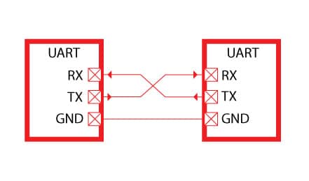
- Configure UART for full duplex (TX and RX).
- Code
- Demo
1.1 Configure UART for full duplex with DMA
In part 1 we discussed how to set the uart to send a single character, we shall use the same initialization sequence.
We started by enabling clock access to USART2 and GPIOA port
RCC->APB1ENR|=RCC_APB1ENR_USART2EN;
RCC->AHB1ENR|=RCC_AHB1ENR_GPIOAEN;
From part one, we concluded that PA2 is the TX pin and PA3 is the RX pin. Hence, we configure them as alternate function and which alternate function as following:
GPIOA->MODER|=(1<<5);//set bit5
GPIOA->MODER&=~(1<<4);//reset bit4

GPIOA->MODER|=(1<<7);//set bit7
GPIOA->MODER&=~(1<<6);//reset bit6

GPIOA->AFR[0]=0x07700; //ALT7 for UART2 (PA2 and PA3)
Now we need to configure the UART
We starting by setting the baud rate to 9600 as following:
USART2->BRR = 0x0681; //9600 @16MHz
Then we enable the TX and RX of the UART as following
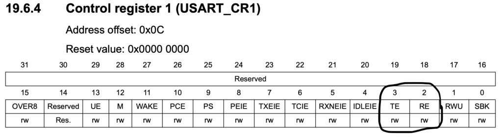
USART2->CR1|=USART_CR1_TE|USART_CR1_RE;
Then enable DMA_TX and DMA_RX in CR3
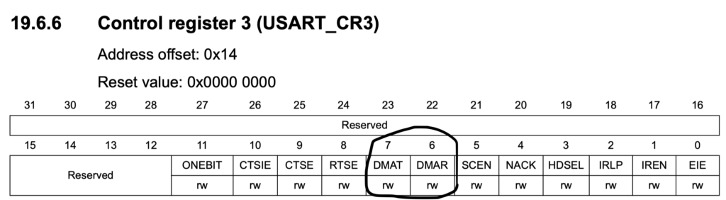
USART2->CR3|=USART_CR3_DMAR|USART_CR3_DMAT;
Then from CR1 we enable transfer complete interrupt as following
USART2->CR1|=USART_CR1_TCIE;
And finally enable UART from CR1
USART2->CR1|=USART_CR1_UE;
1.2 Configure DMA
For UART DMA transmission, please refer to part 4 of the UART guide (here).
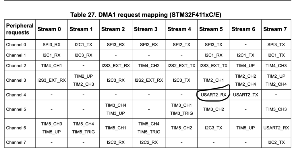
In order to configure DMA to receive data, we need to find which stream and channel of UART_RX is connected to.
From image below, we can see USART2_RX is stream5 channel 4
We start of by enabling clock to DMA as following:
RCC->AHB1ENR |= RCC_AHB1ENR_DMA1EN;
Then disable the current DMA Stream as following
		DMA1_Stream5->CR &= ~1;         /* disable DMA1 Stream 5 */
		while (DMA1_Stream5->CR & 1) {} /* wait until DMA1 Stream 5 is disabled */
clear all interrupt for Stream5
DMA1->HIFCR = 0x00003F00; /* clear all interrupt flags of Stream 5 */
Set the peripheral to be UART2->DR, memory address and number of transfer as following
DMA1_Stream5->PAR =(unsigned int)&USART2->DR;
    DMA1_Stream5->M0AR = (unsigned int)(d);
    DMA1_Stream5->NDTR = sizeof(d);
Next we set the following
- set to channel 4
- Memory and peripheral size to 8-bit
- Memory increment
- Circular mode
- Direction peripheral to memory
- Transfer complete interrupt
- Enable the stream
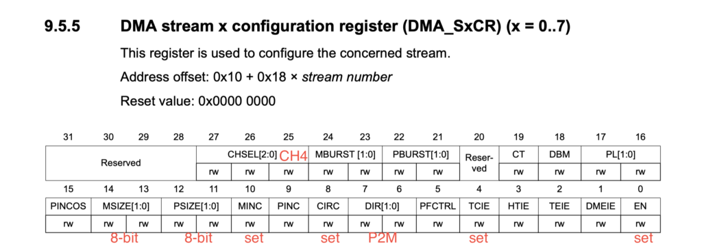
DMA1_Stream5->CR =(1<<27);
		DMA1_Stream5->CR|=(1<<10)|(1<<8)|(1<<4);
		DMA1_Stream5->CR|=(1<<0);
		NVIC_EnableIRQ(DMA1_Stream5_IRQn);  /* DMA interrupt enable at NVIC */
Stream 5 interrupt handler
void DMA1_Stream5_IRQHandler(void)
		{
		if((DMA1->HISR)&(1<<11)) //DMA receive complete
			{
			done_rec=1; //set receive data to
			DMA1->HIFCR|=(1<<11);
			}
		}
in the while loop, if the received data completed, echo back the received data
	if(done_rec==1){
		sprintf(message,"Received characters are %s \r\n",d);
		done_rec=0;
        done = 0;               /* clear done flag */
        DMA1_Stream6_setup((unsigned int)message, (unsigned int)&USART2->DR, strlen(message));
				while (done == 0) {}    /* wait until DMA data transfer is done */
2 Code
Here is the full code
#include "stm32f4xx.h"                  // Device header
#include "string.h"
#include "stdio.h"
void USART2_init(void);
void DMA1_init(void);
void DMA1_Stream6_setup(unsigned int src, unsigned int dst, int len);
void DMA1_Stream5_setup();

int done = 1;
int done_rec=0;
char d[5];
char message [100]={'\0'};

int main (void) {

  USART2_init();
  DMA1_init();
  DMA1_Stream5_setup();
	sprintf(message,"started\r\n");
	 DMA1_Stream6_setup((unsigned int)message, (unsigned int)&USART2->DR, strlen(message));
	while (done == 0) {}    /* wait until DMA data transfer is done */


    while (1) {

	if(done_rec==1){
		sprintf(message,"Received characters are %s \r\n",d);
		done_rec=0;
        done = 0;               /* clear done flag */
        DMA1_Stream6_setup((unsigned int)message, (unsigned int)&USART2->DR, strlen(message));
				while (done == 0) {}    /* wait until DMA data transfer is done */

    }
		}
}

void USART2_init (void) {
    RCC->AHB1ENR |= 1;          /* enable GPIOA clock */
    RCC->APB1ENR |= 0x20000;    /* enable USART2 clock */

		GPIOA->AFR[0]=0x07700; //ALT7 for UART2
		GPIOA->MODER|=0x0080;  //enable PA3 as alternate function
		GPIOA->MODER|=0x0020; //enable PA2 as alterate fuction

    USART2->BRR = 0x0683;       /* 9600 baud @ 16 MHz */
    USART2->CR1 = 0x0008|(1<<2);       /* enable Tx, 8-bit data */
    USART2->CR2 = 0x0000;       /* 1 stop bit */
    USART2->CR3 = 0x0000;       /* no flow control */
    USART2->CR1 |= 0x2000;      /* enable USART2 */
    USART2->CR3 |= (1<<7)|(1<<6);  /* enable USART2 TX/RX DMA */
    USART2->SR = ~0x40;         /* clear TC flag */
    USART2->CR1 |= 0x0040;      /* enable transmit complete interrupt */

    NVIC_EnableIRQ(USART2_IRQn);    /* USART2 interrupt enable at NVIC */
}


void DMA1_init(void) {
    RCC->AHB1ENR |= RCC_AHB1ENR_DMA1EN;     /* DMA controller clock enable */
    DMA1->HIFCR = 0x003F0000;       /* clear all interrupt flags of Stream 6 */
    NVIC_EnableIRQ(DMA1_Stream6_IRQn);  /* DMA interrupt enable at NVIC */
}

void DMA1_Stream5_setup()

	{
		RCC->AHB1ENR |= RCC_AHB1ENR_DMA1EN;
		DMA1_Stream5->CR &= DMA_SxCR_EN;         /* disable DMA1 Stream 5 */
		while (DMA1_Stream5->CR & 1) {} /* wait until DMA1 Stream 5 is disabled */
		DMA1->HIFCR = 0x00003F00;       /* clear all interrupt flags of Stream 5 */
		DMA1_Stream5->PAR =(unsigned int)&USART2->DR;
    DMA1_Stream5->M0AR = (unsigned int)(d);
    DMA1_Stream5->NDTR = sizeof(d);
		DMA1_Stream5->CR =(1<<27);
		DMA1_Stream5->CR|=(1<<10)|(1<<8)|(1<<4);
		DMA1_Stream5->CR|=(1<<0);
		NVIC_EnableIRQ(DMA1_Stream5_IRQn);  /* DMA interrupt enable at NVIC */

	}


void DMA1_Stream6_setup(unsigned int src, unsigned int dst, int len) {

		USART2->SR &= ~USART_SR_TC;          /* clear UART transmit complete interrupt flag */

    DMA1_Stream6->CR &= ~1;         /* disable DMA1 Stream 6 */
    while (DMA1_Stream6->CR & 1) {} /* wait until DMA1 Stream 6 is disabled */
    DMA1->HIFCR = 0x003F0000;       /* clear all interrupt flags of Stream 6 */
    DMA1_Stream6->PAR = dst;
    DMA1_Stream6->M0AR = src;
    DMA1_Stream6->NDTR = len;
    DMA1_Stream6->CR = 0x08000000;  /* USART2_TX on DMA1 Stream6 Channel 4 */
    DMA1_Stream6->CR |= 0x00000440; /* data size byte, mem incr, mem-to-peripheral */
    DMA1_Stream6->CR |= 0x16;       /* enable interrupts DMA_IT_TC | DMA_IT_TE | DMA_IT_DME */
    DMA1_Stream6->CR |= 1;          /* enable DMA1 Stream 6 */
}


void DMA1_Stream6_IRQHandler(void)
{
    if (DMA1->HISR & 0x000C0000)    /* if an error occurred */
        while(1) {}                 /* substitute this by error handling */
    DMA1->HIFCR = 0x003F0000;       /* clear all interrupt flags of Stream 6 */
    DMA1_Stream6->CR &= ~0x10;      /* disable DMA1 Stream 6 TCIE */
}


void USART2_IRQHandler(void)
{
    USART2->SR &= ~0x0040;          /* clear transmit complete interrupt flag */
    done = 1;                       /* set the done flag */
}

void DMA1_Stream5_IRQHandler(void)
		{
		if((DMA1->HISR)&(1<<11)) //DMA receive complete
			{
			done_rec=1;
			DMA1->HIFCR|=(1<<11);
			}
		}
Demo
Add Comment