In the pervious part (from here), we took a look how to send string in UART using polling mode.
In polling mode, we forced the cpu to send the string character by character using software. In this guide, we shall use DMA (Direct Memory Access) to send the string.
In this guide, we will cover the following
- Configure UART for DMA TX
- Configure DMA
- DMA Send
- Code
- Result
1 Configure UART for DMA TX
In order to configure UART to use DMA, we need to enable the DMA Transmission bit in Control Register 3 (CR3).
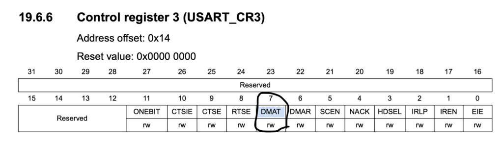
USART2->CR3 |= (1<<7); /* enable USART2 transmitter DMA */
hence, the UART Initialization will be as following
/* Initialize UART pins, Baudrate
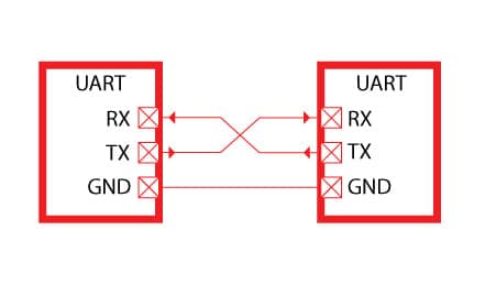
The USART2 is configured to send output to pin PA2 at 9600 Baud.
*/
void USART2_init (void) {
RCC->AHB1ENR |= 1; /* enable GPIOA clock */
RCC->APB1ENR |= 0x20000; /* enable USART2 clock */
/* Configure PA2 for USART2_TX */
GPIOA->AFR[0] &= ~0x0F00;
GPIOA->AFR[0] |= 0x0700; /* alt7 for USART2 */
GPIOA->MODER &= ~0x0030;
GPIOA->MODER |= 0x0020; /* enable alternate function for PA2 */
USART2->BRR = 0x0683; /* 9600 baud @ 16 MHz */
USART2->CR1 = 0x0008; /* enable Tx, 8-bit data */
USART2->CR2 = 0x0000; /* 1 stop bit */
USART2->CR3 = 0x0000; /* no flow control */
USART2->CR1 |= 0x2000; /* enable USART2 */
USART2->CR3 |= (1<<7); /* enable USART2 transmitter DMA */
USART2->SR = ~0x40; /* clear TC flag */
USART2->CR1 |= 0x0040; /* enable transmit complete interrupt */
NVIC_EnableIRQ(USART2_IRQn); /* USART2 interrupt enable at NVIC */
}2.1 DMA Initialization
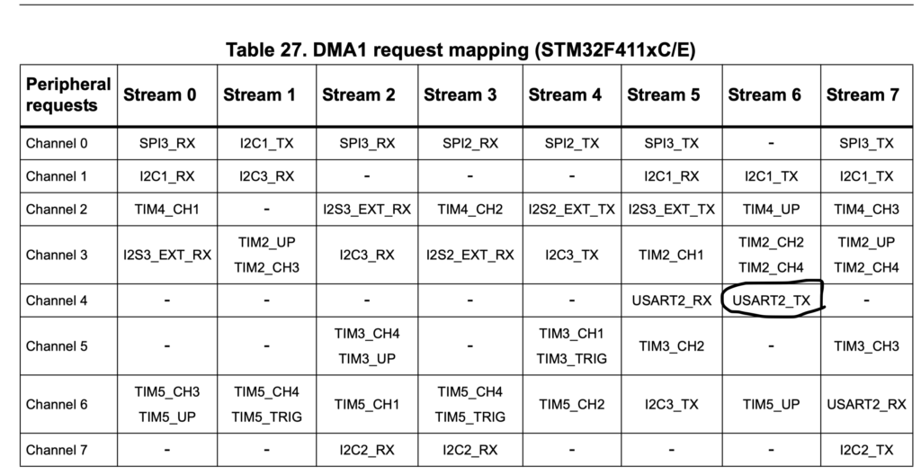
Before we enable clock access, we need to know which DMA and which channel to use in order to use DMA for UART TX.
From DMA section from reference manual of STM32F411, we conclude the we need to use DMA1 Stream6 and channel 4
First we start by enabling clock access to DMA1 as following
RCC->AHB1ENR |= RCC_AHB1ENR_DMA1EN; /* DMA controller clock enable */
Then we clear all pending interrupts of DMA1_Stream 6 (HIFCR)
DMA1->HIFCR = 0x003F0000; /* clear all interrupt flags of Stream 6 */
Finally enable interrupt for DMA1_Stream6
NVIC_EnableIRQ(DMA1_Stream6_IRQn); /* DMA interrupt enable at NVIC */
2.2 DMA Configuration to send data
First we need clear the Transmission Complete interrupt from status register of USART2 as following
USART2->SR &= ~USART_SR_TC; /* clear UART transmit complete interrupt flag */
Then we disable the stream and wait until the stream is disabled
DMA1_Stream6->CR &= ~1;         /* disable DMA1 Stream 6 */
 while (DMA1_Stream6->CR & 1) {} /* wait until DMA1 Stream 6 is disabled */
We clear the interrupt flags of DMA1_Stream6
DMA1->HIFCR = 0x003F0000; /* clear all interrupt flags of Stream 6 */
Then we set the destination as following
DMA1_Stream6->PAR = dst;
Setting the source as following
DMA1_Stream6->M0AR = src;
Setting how many number of bytes to send as following
DMA1_Stream6->NDTR = len;
Now we choose channel 4
DMA1_Stream6->CR = 0x08000000; /* USART2_TX on DMA1 Stream6 Channel 4 */
now we select memory size, memory inc and memory to peripheral as following
DMA1_Stream6->CR |= 0x00000440; /* data size byte, mem incr, mem-to-peripheral */
Now we need to enable some interrupt
- Transfer complete interrupt enable
- Transfer error interrupt enable
- Direct mode error interrupt enable
DMA1_Stream6->CR |= 0x16; /* enable interrupts DMA_IT_TC | DMA_IT_TE | DMA_IT_DME */
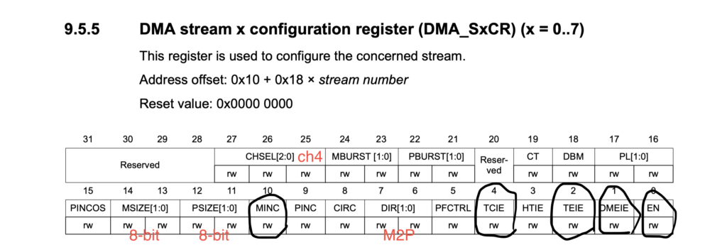
Finally we enable the DMA stream.
DMA1_Stream6->CR |= 1; /* enable DMA1 Stream 6 */
2.3 Interrupt handler
For interrupt handler. For DMA, in case of error it will halt the entire mcu and for UART if the TC is triggered , we inform the application that the transmission is finished
/*  DMA1 Stream6 interrupt handler
    This function handles the interrupts from DMA1 controller Stream6. The error interrupts
    have a placeholder for error handling code. If the interrupt is from DMA data
    transfer complete, the DMA controller is disabled, the interrupt flags are
    cleared.
 */
void DMA1_Stream6_IRQHandler(void)
{
    if (DMA1->HISR & 0x000C0000)    /* if an error occurred */
        while(1) {}                 /* substitute this by error handling */
    DMA1->HIFCR = 0x003F0000;       /* clear all interrupt flags of Stream 6 */
    DMA1_Stream6->CR &= ~0x10;      /* disable DMA1 Stream 6 TCIE */
}

/*  USART2 interrupt handler
 *  USART2 transmit complete interrupt is used to set the done flag to signal
 *  the other part of the program that the data transfer is done.
 */
void USART2_IRQHandler(void)
{
    USART2->SR &= ~0x0040;          /* clear transmit complete interrupt flag */
    done = 1;                       /* set the done flag */

}
3. Code
#include "stm32f4xx.h"                  // Device header
#include "string.h"
#include "stdio.h"
void USART2_init(void);
void DMA1_init(void);
void DMA1_Stream6_setup(unsigned int src, unsigned int dst, int len);
int variable;
int done = 1;
char c[]="hello from stm32f411re \r\n";
char message[sizeof(c)];


void delayMs(int delay)

{

int i;

for(; delay>0 ;delay--)

{

for(i =0; i<3195;i++);

}

}


int main (void) {


    USART2_init();
    DMA1_init();

    while (1) {

			int i;
    int size = strlen(c);
        /* prepare the message for transfer */

        for (i = 0; i < size; i++)
            message[i] = c[i];

        /* send the message out by USART2 using DMA */
        while (done == 0) {}    /* wait until DMA data transfer is done */
        done = 0;               /* clear done flag */
        DMA1_Stream6_setup((unsigned int)message, (unsigned int)&USART2->DR, size);

    }
}
/*  Initialize UART pins, Baudrate
    The USART2 is configured to send output to pin PA2 at 9600 Baud.
 */
void USART2_init (void) {
    RCC->AHB1ENR |= 1;          /* enable GPIOA clock */
    RCC->APB1ENR |= 0x20000;    /* enable USART2 clock */

    /* Configure PA2 for USART2_TX */
    GPIOA->AFR[0] &= ~0x0F00;
    GPIOA->AFR[0] |=  0x0700;   /* alt7 for USART2 */
    GPIOA->MODER  &= ~0x0030;
    GPIOA->MODER  |=  0x0020;   /* enable alternate function for PA2 */

    USART2->BRR = 0x0683;       /* 9600 baud @ 16 MHz */
    USART2->CR1 = 0x0008;       /* enable Tx, 8-bit data */
    USART2->CR2 = 0x0000;       /* 1 stop bit */
    USART2->CR3 = 0x0000;       /* no flow control */
    USART2->CR1 |= 0x2000;      /* enable USART2 */
    USART2->CR3 |= (1<<7);            /* enable USART2 transmitter DMA */
    USART2->SR = ~0x40;         /* clear TC flag */
    USART2->CR1 |= 0x0040;      /* enable transmit complete interrupt */

    NVIC_EnableIRQ(USART2_IRQn);    /* USART2 interrupt enable at NVIC */
}


/*  Initialize DMA1 controller
 *  DMA1 controller's clock is enabled and also the DMA interrupt is
 *  enabled in NVIC.
 */
void DMA1_init(void) {
    RCC->AHB1ENR |= RCC_AHB1ENR_DMA1EN;     /* DMA controller clock enable */
    DMA1->HIFCR = 0x003F0000;       /* clear all interrupt flags of Stream 6 */


    NVIC_EnableIRQ(DMA1_Stream6_IRQn);  /* DMA interrupt enable at NVIC */
}

/*  Set up a DMA transfer for USART2
 *  The USART2 is connected to DMA1 Stream 6. This function sets up the
 *  peripheral register address, memory address, number of transfers,
 *  data size, transfer direction, and DMA interrupts are enabled.
 *  At the end, the DMA controller is enabled and the USART2 transmit
 *  DMA is enabled.
 */
void DMA1_Stream6_setup(unsigned int src, unsigned int dst, int len) {

		USART2->SR &= ~USART_SR_TC;          /* clear UART transmit complete interrupt flag */

    DMA1_Stream6->CR &= ~1;         /* disable DMA1 Stream 6 */
    while (DMA1_Stream6->CR & 1) {} /* wait until DMA1 Stream 6 is disabled */
    DMA1->HIFCR = 0x003F0000;       /* clear all interrupt flags of Stream 6 */
    DMA1_Stream6->PAR = dst;
    DMA1_Stream6->M0AR = src;
    DMA1_Stream6->NDTR = len;
    DMA1_Stream6->CR = 0x08000000;  /* USART2_TX on DMA1 Stream6 Channel 4 */
    DMA1_Stream6->CR |= 0x00000440; /* data size byte, mem incr, mem-to-peripheral */
    DMA1_Stream6->CR |= 0x16;       /* enable interrupts DMA_IT_TC | DMA_IT_TE | DMA_IT_DME */
    //DMA1_Stream6->FCR  = 0;         /* direct mode, no FIFO */
    DMA1_Stream6->CR |= 1;          /* enable DMA1 Stream 6 */


}

/*  DMA1 Stream6 interrupt handler
    This function handles the interrupts from DMA1 controller Stream6. The error interrupts
    have a placeholder for error handling code. If the interrupt is from DMA data
    transfer complete, the DMA controller is disabled, the interrupt flags are
    cleared.
 */
void DMA1_Stream6_IRQHandler(void)
{
    if (DMA1->HISR & 0x000C0000)    /* if an error occurred */
        while(1) {}                 /* substitute this by error handling */
    DMA1->HIFCR = 0x003F0000;       /* clear all interrupt flags of Stream 6 */
    DMA1_Stream6->CR &= ~0x10;      /* disable DMA1 Stream 6 TCIE */
}

/*  USART2 interrupt handler
 *  USART2 transmit complete interrupt is used to set the done flag to signal
 *  the other part of the program that the data transfer is done.
 */
void USART2_IRQHandler(void)
{
    USART2->SR &= ~0x0040;          /* clear transmit complete interrupt flag */
    done = 1;                       /* set the done flag */

}
4. Results
after you compile and upload the code, you will get this
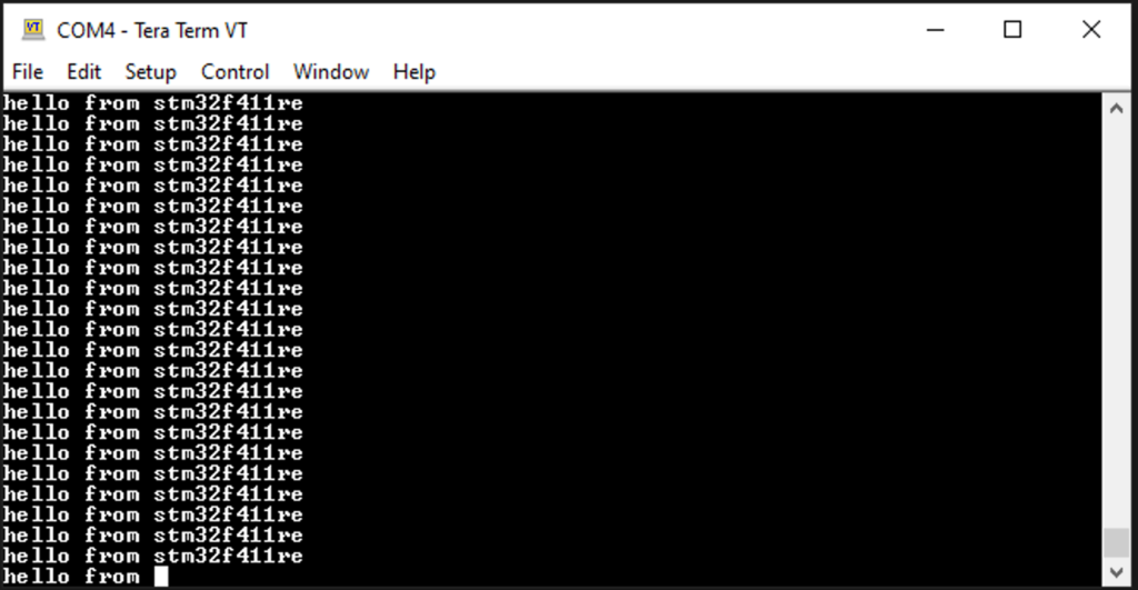
Add Comment