In the pervious two guides (part 1 & part 2 ) how to send a single character and string using UART. In this guide, we shall discuss how to receive a character from UART using interrupt handler and echo back the sent character and blink the internal led number of times according to the sent number.
In this guide, we will cover the following:
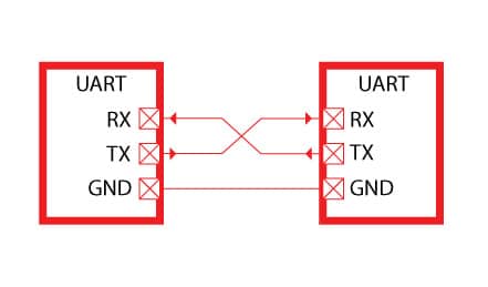
- Configure UART for full duplex (TX and RX).
- Code
- Demo
1. Configure UART for full duplex
In part 1 we discussed how to set the uart to send a single character, we shall use the same initialization sequence.
We started by enabling clock access to USART2 and GPIOA port
RCC->APB1ENR|=RCC_APB1ENR_USART2EN;
RCC->AHB1ENR|=RCC_AHB1ENR_GPIOAEN;
From part one, we concluded that PA2 is the TX pin and PA3 is the RX pin. Hence, we configure them as alternate function and which alternate function as following:
GPIOA->MODER|=(1<<5);//set bit5
GPIOA->MODER&=~(1<<4);//reset bit4

GPIOA->MODER|=(1<<7);//set bit7
GPIOA->MODER&=~(1<<6);//reset bit6

GPIOA->AFR[0]=0x07700; //ALT7 for UART2 (PA2 and PA3)
Now we need to configure the UART
We starting by setting the baud rate to 9600 as following:
USART2->BRR = 0x0681; //9600 @16MHz
then selecting the UART to enable TX, RX and RXNEIE (Receiver interrupt) in Control Register 1 (CR1) and enabling UART module as following:
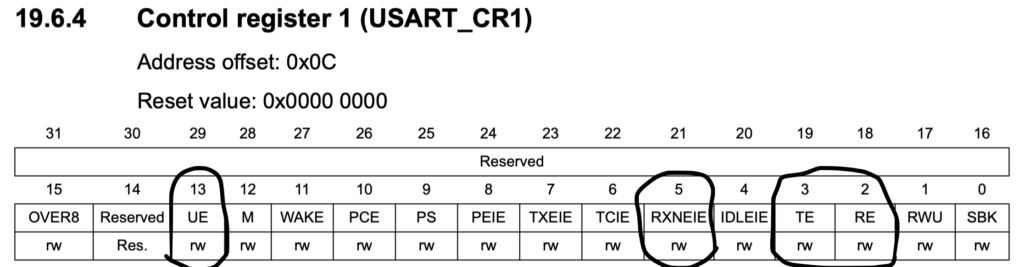
Hence, the configuration shall be as following:
USART2->CR1 |= (1<<2)|(1<<3)|(1<<5)|(1<<13);
After than we shall enable the interrupt of USART in NVIC as following
NVIC_EnableIRQ(USART2_IRQn);
Now for the interrupt handler
void USART2_IRQHandler(void){

if(USART2->SR&0x0020) //check if the read data register is not empty
{
c=USART2->DR; //store current data in variable c
}
}
2. Code
#include "stm32f4xx.h"                  // Device header
void delay(int delayms);
void led_play(int value);
void UART2_Init();
void USART2_IRQHandler(void);
void USART2_write(int ch);
char c;
int main ()
{
__disable_irq();
UART2_Init();
GPIOA->MODER|= GPIO_MODER_MODER5_0; //PA5 as output
USART2->CR1|=0x0020;

__enable_irq();

while(1)
{
if(c!=' '){
led_play(c);
USART2_write(c);
USART2_write('\r');
USART2_write('\n');
c=' ';
}
}

}

void led_play(int value)
{
value %=16;
	for (;value>0;value--){
	GPIOA->BSRR|=GPIO_BSRR_BS5; //turn on ledd
		delay(100);
		GPIOA->BSRR|=GPIO_BSRR_BR5; //turn off the led
		delay(100);
	}
}

void delay(int delayms){
SysTick->LOAD=16000-1;
SysTick->VAL=0;
SysTick->CTRL=0x5;
for (int i=0;i<delayms;i++)
{
while(!(SysTick->CTRL &0x10000)){}
		}
	SysTick->CTRL=0;
}

void UART2_Init(){
	RCC->AHB1ENR |=1; //Enable GPIOA clock
	RCC->APB1ENR|=0x20000; //Enable USART clock
	//configure PA3 as alternative function
	GPIOA->AFR[0]=0x07700; //ALT7 for UART2
	GPIOA->AFR[1]=0x07000;
	GPIOA->MODER|=0x0080;  //enable PA3 as alternate function
	GPIOA->MODER|=0x0020; //enable PA2 as alterate fuction
	USART2->BRR=0x008B; // set baud rate of 115200 for 16MHz
	USART2->CR1|=0x0020;
	USART2->CR1|=0x200C; //enable RX
	NVIC_EnableIRQ(USART2_IRQn);
}

void USART2_IRQHandler(void){

if(USART2->SR&0x0020){
c=USART2->DR;
}
}
void USART2_write(int ch){

while(!(USART2->SR&0x0080)){
}
USART2->DR=(ch&0xff);
}
Add Comment