
In this guide, we shall see how output compare mode works and develop a driver that will toggle the LED using hardware.
In this guide, we shall cover the following:
- Timer in output compare.
- Micropython Firmware.
- Hardware Conenction
- Results.
1. Timer in Output Compare:
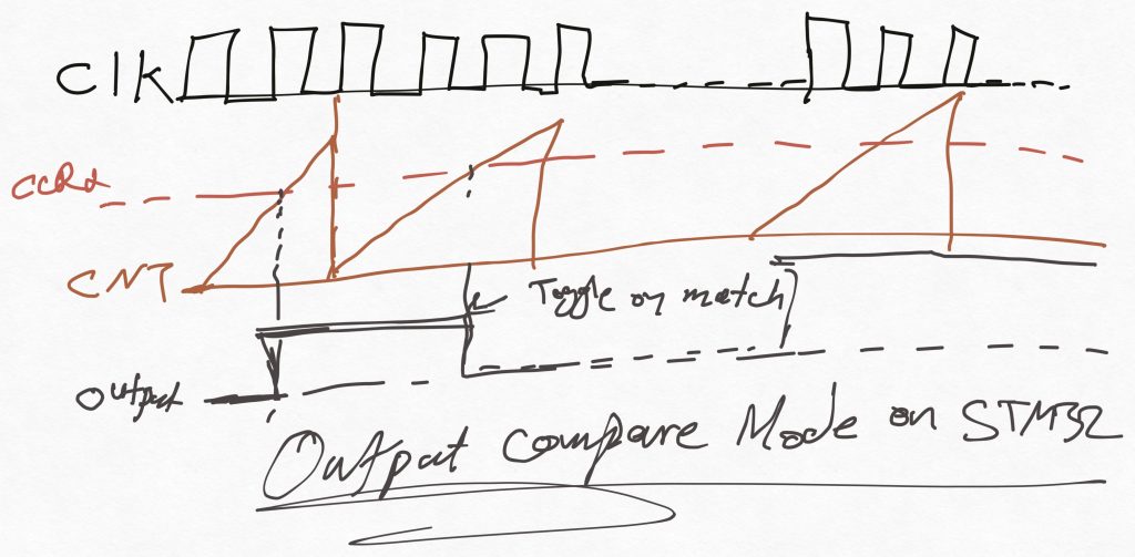
The Output Compare concept in STM32 is based on comparing the timer’s counter value with a predefined value (stored in a capture/compare register) to trigger an event or perform an action. It’s used for precise timing, periodic signals, and PWM generation.
Core Concept:
1. Timer Counting:
• A timer counts up, down, or both (depending on the mode).
• The current count value is stored in the Counter Register (CNT).
2. Comparison:
• A predefined value is stored in a Compare Register (CCR).
• The timer continuously compares the CNT value with CCR.
3. Match Event:
• When CNT == CCR, the timer generates a match event.
• The event can trigger an action (e.g., toggling a pin, generating an interrupt, or updating a PWM signal).
Use Cases:
• Generating Periodic Signals: Toggle a GPIO pin at regular intervals.
• PWM Signal Generation: Control duty cycles for motor drivers or LED dimming.
• Input Capture Synchronization: Measure or synchronize external signal timing.
• Event Timing: Trigger specific actions at predefined time intervals.
Output Compare Modes:
1. Toggle Mode: Changes the GPIO pin state (high/low) on each match.
2. Set Mode: Forces the GPIO pin high when a match occurs.
3. Reset Mode: Forces the GPIO pin low when a match occurs.
4. PWM Mode: Outputs a pulse-width-modulated signal, varying the on/off times.
Key Features:
• Resolution: Depends on the timer’s bit width (16-bit or 32-bit).
• Precision: Achieved using the timer’s prescaler to adjust clock speed.
• Flexibility: Multiple channels per timer for simultaneous compare events.
• Interrupts: Can trigger interrupts on compare match for software-driven actions.
Example in Words:
• A timer is configured to count from 0 to 1000 (auto-reload value).
• A compare value of 500 is set in CCR1.
• When the timer reaches 500, it toggles a GPIO pin (or triggers an interrupt).
• The process repeats as the timer resets and counts again.
By using Output Compare, you can control real-time events with high precision, critical in embedded systems like motor control, signal generation, or sensor sampling.
We shall use toggle Mode to blink an LED.
2. Micropython Firmware:
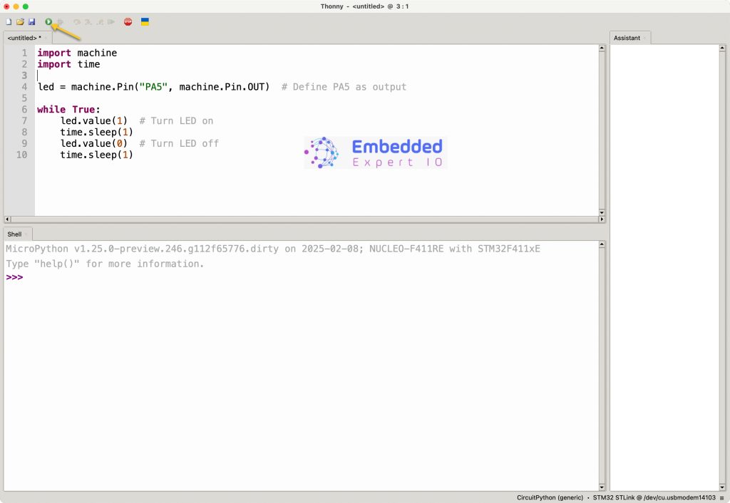
First, we need to configure Thonny to work with STM32F411 Nucleo-64. Please refer to this guide for how to install and configure Thonny.
First, we need to find which pins are connected to TIM2. From the datasheet of the STM32F411RE, we can find that PA0 to PA3 are connected to TIM2_CH1 to TIM2_CH4 respectively.
However, PA2 and PA4 are used for UART for micropython core. Hence, they can’t be used in out firmware.
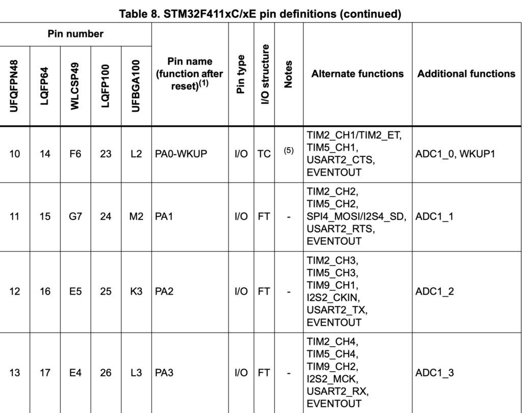
After finding which pins are connected to TIM2, we shall use PA0 as our PWM pin.
We start by importing pyb (pyboard) as following:
import pyb
Next, setup timer 2 as following:
timer2 = pyb.Timer(2, freq=1) # Set Timer 2 at 1 Hz
Next, configure the channel of the timer to work as output compare as following:
ch1 = timer2.channel(1, pyb.Timer.OC_TOGGLE, pin=pyb.Pin.board.PA0, pulse_width_percent=0)
The function takes the following:
- Channel number which is channel 1.
- Timer mode which is OC_Toggle in this case.
- Required pin which is PA0.
- Width which is set to 0 in this case.
You can change the mode from Timer.OC_TOGGLE to:
Timer.OC_ACTIVE: Output is high when compare match occurs.Timer.OC_INACTIVE: Output is low when compare match occurs.Timer.OC_FORCE_ACTIVE: Forces output high.Timer.OC_FORCE_INACTIVE: Forces output low.
Thats all for the driver.
Click on run as following:
3. Hardware Connection:
The connection as following:

Since PA0 is connected to A0 pin of the arduino pins. Hence, we shall connect our LED to this pin.
Don’t forger to add 220Ohm to limit the current.
4. Results:
You should get something similar to this:
Happy coding 😉
Add Comment