This guide demonstrates how to configure an external GPIO interrupt on the STM32H5 Nucleo-144 board. You’ll learn how to connect a push-button and trigger an interrupt using STM32CubeMX and HAL libraries.
In this guide, we shall cover the following:
- What is external interrupt.
- STM32CubeIDE setup.
- Firmware development.
- Results.
1. What is External Interrupt:
External Interrupts :
External interrupts come from input-output I/O devices.
Some examples that cause external interrupts:
- I/O devices requesting transfer of data
- I/O devices finished the transfer of data. When a program executes in an endless loop and thus exceeds its time limit, an external interrupt occurs which is Timeout Interrupt.
- While transferring the CPU’s complete state to a non-destructive memory in a few milliseconds before power ceases, then an external interrupt occurs.
Advantages of External Interrupts
- Increased Flexibility: External interrupts allow a system to respond to external events, such as a user input or an external sensor, in real-time. This can greatly improve the system’s flexibility, as it is not limited to a fixed operating cycle.
- Ability to Respond to External Events: External interrupts provide a mechanism for the system to respond to external events that may occur at any time. This allows the system to perform tasks in response to changes in the environment, such as user input or incoming data, without the need for continuous monitoring.
- Improved Performance and Efficiency: By allowing the system to respond to external events in real-time, external interrupts can greatly improve the system’s performance and efficiency, as it is not bogged down by continuous monitoring for changes.
Applications of External Interrupts
- Input Devices: External interrupts are commonly used in input devices, such as keyboards, mice, and touchpads, to respond to user input in real-time.
- Data Acquisition Systems: External interrupts can be used in data acquisition systems to respond to incoming data and process it in real-time.
- Robotics: External interrupts can be used in robotics systems to respond to external events, such as sensor inputs or user commands.
- Real-time Systems: External interrupts are commonly used in real-time systems, such as process control systems and medical equipment, to provide a mechanism for responding to external events in real-time.
2. STM32CubeIDE Setup:
Before we start, we need to find some information about H563Zi-Nucleo-144 board, mainly the push button and LEDs.
From the schematic of the board, we can find the following:
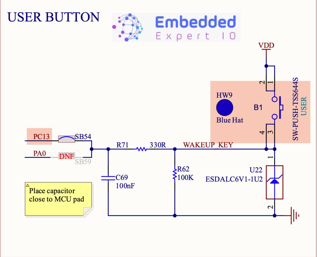
We can find that the blue button is connected to PC13 and it is has pull-down resistor which means when pressed, the state on the GPIO pin will be high (3.3V) and when released will be low (0V).
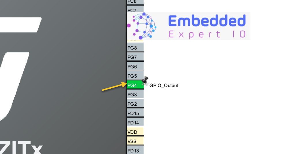
Also, we shall use the user LEDs.
We shall nominate the red led for this guide.
The red LED is connected to PG4 as shown below:

We start off by creating new project with name of Internal EXTI. For how to create project using STM32CubeIDE, please refer to this guide here.
After creating the project, the STM32CubeMX configuration window will appear.
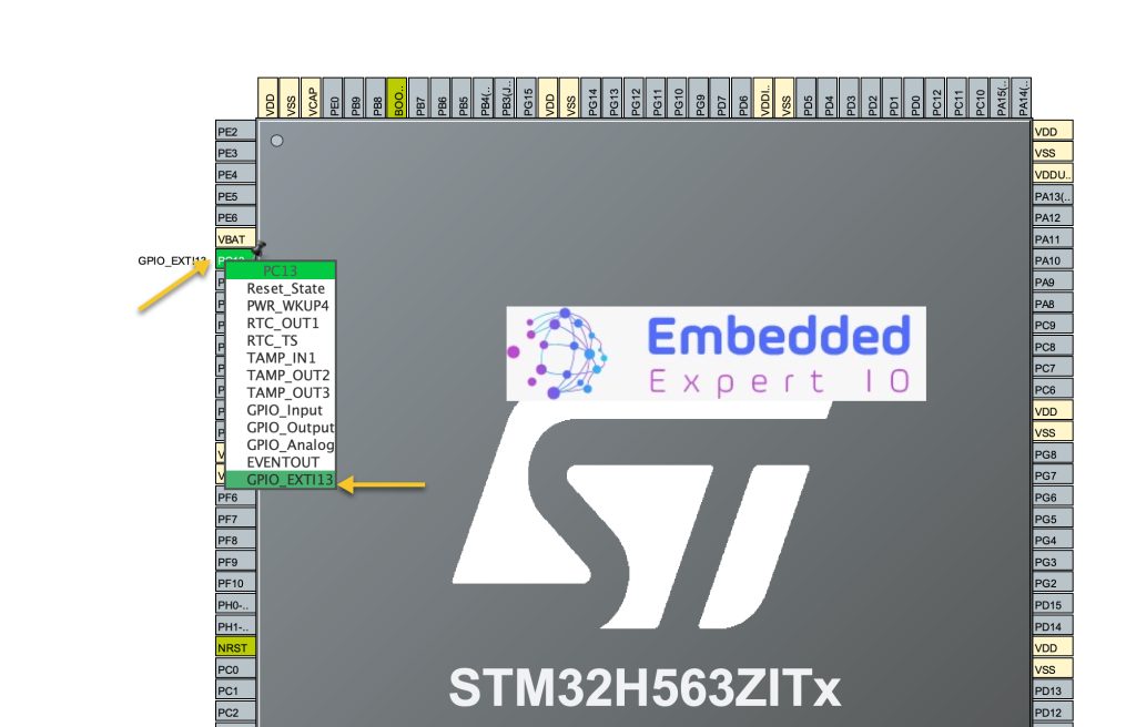
Set PC13 as GPIO_EXTI13 as following:
Also, set PG4 as output where the LED is connected as following:
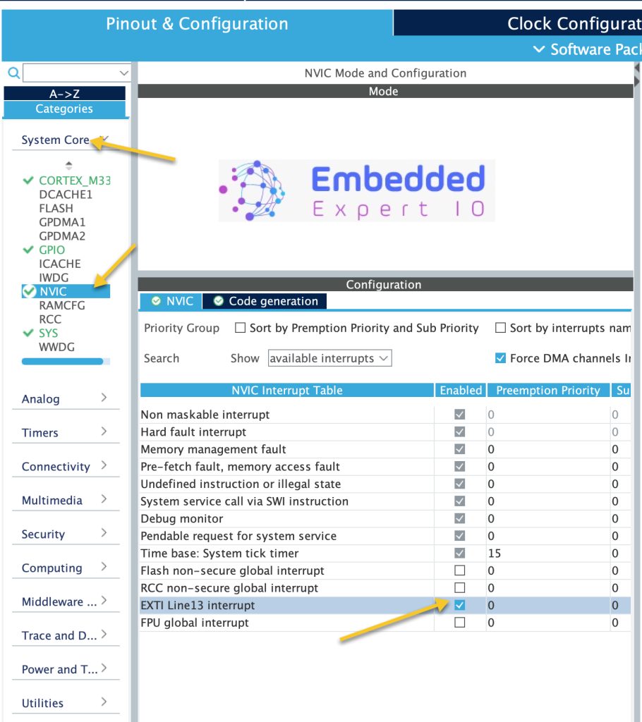
Next, from System Core Select NVIC as enable EXTI Line13 Interrupt as following:
Next, go to GPIO, select PC13 and set the edge to be rising edge as following:
Note: STM32 supports the following:
- Rising edge (Go from 0 to 3.3V).
- Falling edge (Go from 3V3 to 0).
- Rising and falling edge.
Thats all for the configuration.
Save the project and this will generate the code.
3. Firmware Development:
After the project has been generated.
In use code begin 4 in main.c:
When the external interrupt is generated, one of these two function define as weak shall be called:
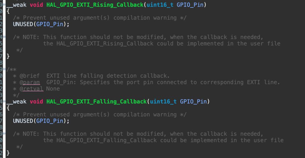
These functions are define in stm32h5xx_hal_gpio.c source file.
Since the external interrupt is configured as rising edge, the Rising callback function shall be called.
Hence, in user code begin 4:
void HAL_GPIO_EXTI_Rising_Callback(uint16_t GPIO_Pin)
{
	if(GPIO_Pin==GPIO_PIN_13)
	{
		HAL_GPIO_TogglePin(GPIOG,GPIO_PIN_4);
	}
}
In the interrupt, check if it is pin 13, if it, toggle the LED.
That all for this guide.
Save the project, build and run it on your board.

4. Result:
You should get the following when you press the button.
Happy coding 😉
Add Comment