In this series guide of STM32H5, we shall see how to develop drivers using STM32CubeMX for STM32H563ZI Nucleo-144.
In this guide, we shall cover the following:
- Features of STM32H563Zi.
- Feature of STM32H563ZI Nucleo-144.
- Creating new project.
- First project, blink an LED.
- Results.
1. Feature of STM32H563Zi:
All features
- Core
- Arm® Cortex®-M33 CPU with TrustZone®, FPU, frequency up to 250 MHz, MPU, 375 DMIPS (Dhrystone 2.1)
- ART Accelerator
- 8-Kbyte instruction cache allowing 0-wait-state execution from flash and external memories
- 4-Kbyte data cache for external memories
- Benchmarks
- 1.5 DMIPS/MHz (Drystone 2.1)
- 1023 CoreMark® (4.092 CoreMark®/MHz)
- Memories
- Up to 2 Mbytes of embedded flash memory with ECC, two banks read-while-write
- Up to 48-Kbyte per bank with high-cycling capability (100 K cycles) for data flash
- 2-Kbyte OTP (one-time programmable)
- 640 Kbytes of SRAM (64-Kbyte SRAM2 with ECC and 320-Kbyte SRAM3 with flexible ECC)
- 4 Kbytes of backup SRAM available in the lowest power modes
- Flexible external memory controller with up to 16-bit data bus: SRAM, PSRAM, FRAM, SDRAM/LPSDR SDRAM, NOR/NAND memories
- One Octo-SPI memory interface with support for serial PSRAM/NAND/NOR, hyper RAM/flash frame formats
- Two SD/SDIO/MMC interfaces
- Clock management
- Internal oscillators: 64 MHz HSI, 48 MHz HSI48, 4 MHz CSI, 32 kHz LSI
- External oscillators: 4-50 MHz HSE, 32.768 kHz LSE
- General-purpose inputs/outputs
- Up to 140 fast I/Os with interrupt capability (most 5 V tolerant)
- Up to ten I/Os with independent supply down to 1.08 V
- Low-power consumption
- Sleep, Stop, and Standby modes
- VBAT supply for RTC, 32 backup registers (32-bit)
- Security
- Arm® TrustZone® with Armv8-M mainline security extension
- Up to eight configurable SAU regions
- TrustZone® aware and securable peripherals
- Flexible life cycle scheme with secure debug authentication
- SFI (secure firmware installation)
- Secure firmware upgrade support with TF-M
- HASH hardware accelerator
- ECDSA signature verification
- True random number generator, NIST SP800-90B compliant
- 96-bit unique ID
- Active tampers
- Two DMA controllers to offload the CPU
- Two dual-port DMAs with FIFO
- Mathematical acceleration
- CORDIC for trigonometric functions acceleration
- FMAC (filter mathematical accelerator)
- Reset and supply management
- 1.71 V to 3.6 V application supply and I/O
- POR, PDR, PVD, and BOR
- Embedded regulator (LDO) or SMPS step-down converter regulator with configurable scalable output to supply the digital circuitry
- Up to 24 timers
- 18 16-bit (including six low-power 16-bit timers available in Stop mode)
- Two 32-bit timers with up to four IC/OC/PWM or pulse counters and quadrature (incremental) encoder input
- Two watchdogs
- Two SysTick timers
- Up to 34 communication interfaces
- Up to four I2Cs Fm+ (SMBus/PMBus®)
- One I3C
- Up to 12 U(S)ARTs (ISO7816 interface, LIN, IrDA, modem control) and one LPUART
- Up to six SPIs, including three muxed full-duplex I2S audio class accuracy via internal audio PLL or external clock, and up to five additional SPIs from five USARTs when configured in Synchronous mode (one additional SPI with OctoSPI)
- Two SAIs
- Two FDCANs
- One 8- to 14-bit camera interface
- One 16-bit parallel slave synchronous-interface
- One HDMI-CEC
- One Ethernet MAC interface with DMA controller
- One USB 2.0 full-speed host and device
- One USB Type-C®/USB Power Delivery r3.1
- Analog
- Two 12-bit ADCs with up to 5 Msps in 12-bit
- Two 12-bit DACs
- Digital temperature sensor
- Debug
- Authenticated debug and flexible device life cycle
- Serial wire-debug (SWD), JTAG, Embedded Trace Macrocell™ (ETM)
- ECOPACK2 compliant packages
Block diagram of STM32H563ZI:
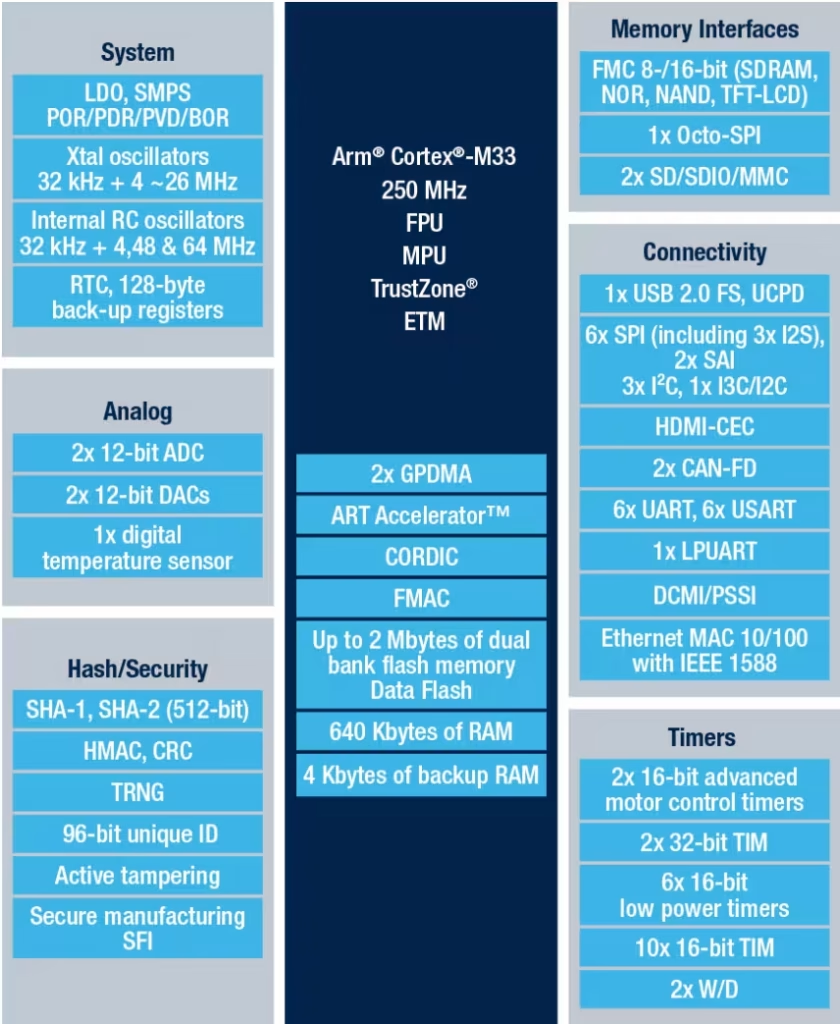
Note: Features and block diagram have been taken from ST website: https://www.st.com/en/microcontrollers-microprocessors/stm32h563zi.html
2. Feature of STM32H563ZI Nucleo-144:
All features
- Common features
- STM32 microcontroller in an LQFP144 or a TFBGA225 package
- 3 user LEDs
- 2 user and reset push-buttons
- 32.768 kHz crystal oscillator
- Board connectors:
- SWD
- ST Zio expansion connector including ARDUINO® Uno V3
- ST morpho expansion connector
- Flexible power-supply options: ST-LINK USB VBUS, USB connector, or external sources
- Comprehensive free software libraries and examples available with the STM32Cube MCU Package
- Support of a wide choice of Integrated Development Environments (IDEs) including IAR Embedded Workbench®, MDK-ARM, and STM32CubeIDE
- Features specific to some of the boards
- External or internal SMPS to generate Vcore logic supply:NUCLEO-L496ZG-P, NUCLEO-L4R5ZI-P, NUCLEO-L552ZE-Q, NUCLEO-H745ZI-Q, NUCLEO-H755ZI-Q, NUCLEO-H7A3ZI-Q, NUCLEO-U575ZI-Q, and NUCLEO-U5A5ZJ-Q
- Ethernet compliant with IEEE-802.3-2002:NUCLEO-F207ZG, NUCLEO-F429ZI, NUCLEO-F439ZI, NUCLEO-F746ZG, NUCLEO-F756ZG, NUCLEO-F767ZI, NUCLEO-H563ZI, NUCLEO-H723ZG, NUCLEO-H743ZI, NUCLEO-H743ZI2, NUCLEO-H745ZI-Q, NUCLEO-H753ZI, NUCLEO-H755ZI-Q, and NUCLEO-H7S3L8
- USB Device only, USB OTG full speed, or SNK/UFP (full-speed or high-speed mode)
- Board connectors:
- MIPI20 compatible connector with trace signals (NUCLEO-H7S3L8)
- USB with Micro-AB or USB Type-C®
- Ethernet RJ45
- On-board ST-LINK (STLINK/V2-1, STLINK-V3E, or STLINK-V3EC) debugger/programmer with USB re-enumeration capability: mass storage, Virtual COM port, and debug port
Note: These features have been taken from ST website: https://www.st.com/en/evaluation-tools/nucleo-h563zi.html#overview
3. Creating New Project:
First, download and install the latest STM32CubeIDE from here.
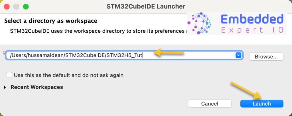
After installing the IDE, open the IDE and it will ask you create workspace.
Call this workspace as STM32H5_Tut (Can be any name you want) and click on launch:
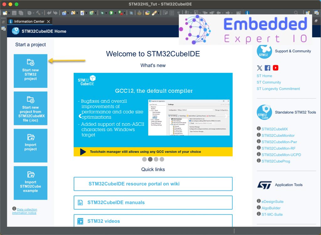
Next, click on Start new STM32 Project as following:
Next search the STM32H563ZI and select the one with Nucleo-144 as following:
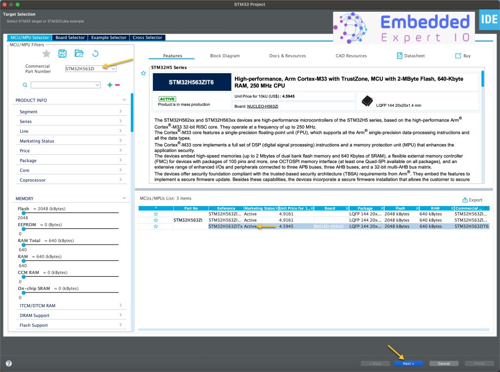
Note: Select the bare bone chip not the Nucleo-144.
Click on Next and give the project a name and click on finish.
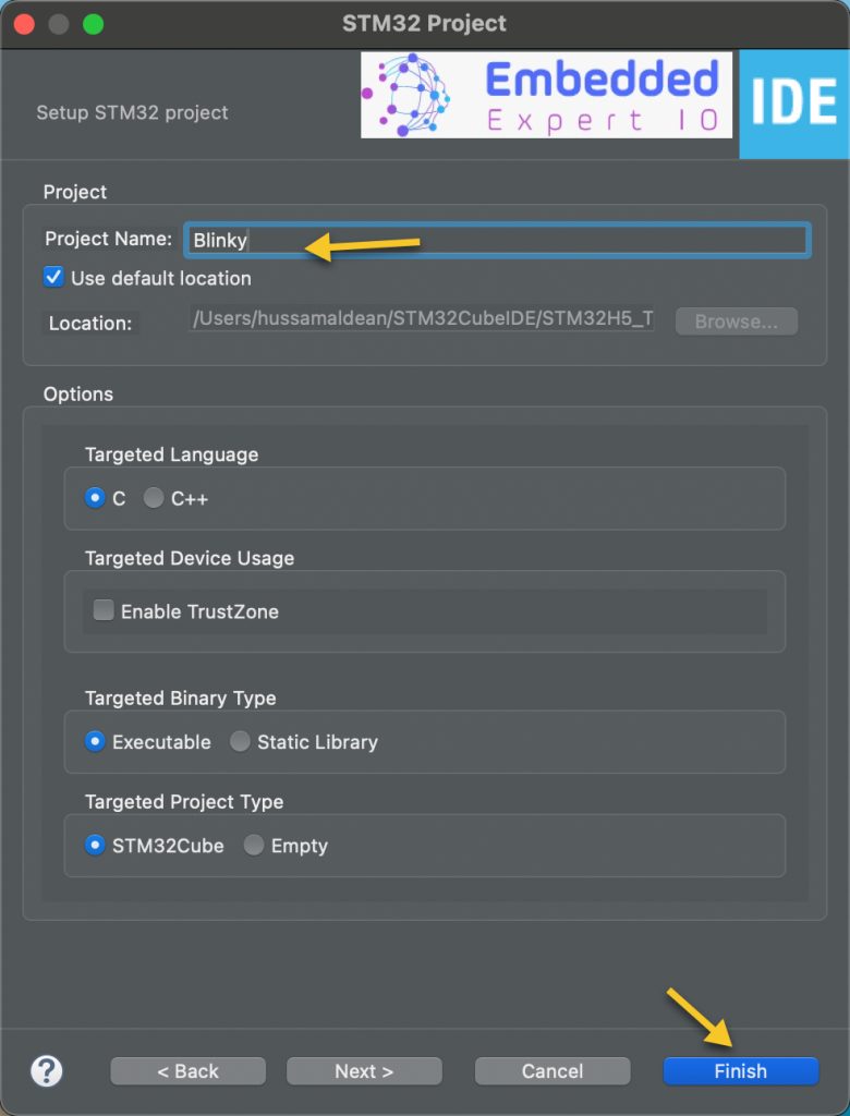
Now the project is created.
Note: During the creating of the project, it will ask you the following:
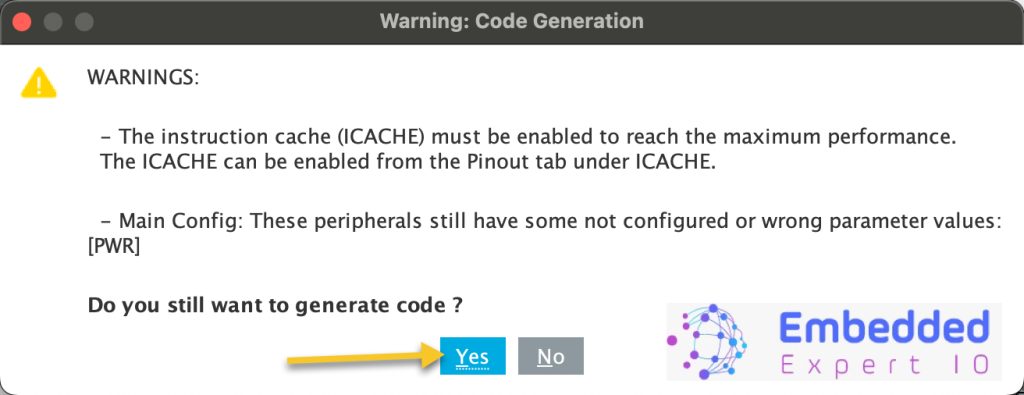
Just click on yes.
3. First Project: Blink an LED:
Since this Nucleo-144 board features 3 LEDs. We need to know which pins are connected to these LED, in order to find these pins, we need to take a look at the schematic of the board.
Go to the STM32H563ZI Nucleo-144 website from here.
Next, select CAD and then the schematic as following:
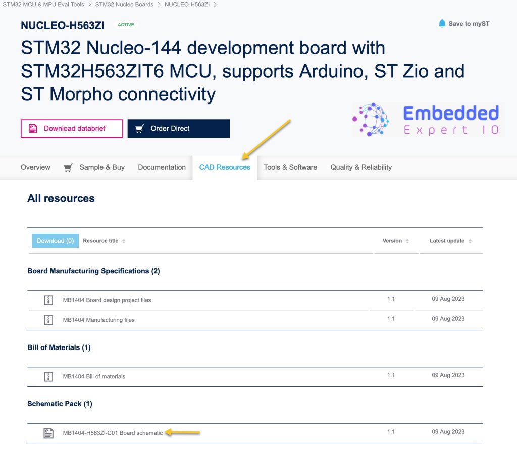
This will download the pdf file.
Then from the schematic pdf file:

From the schematic:
- Green LED is connected to PB0.
- Yellow LED is connected to PF4.
- Red LED is connected to PG4.
In this guide, we shall use the green LED which is connected to PB0.
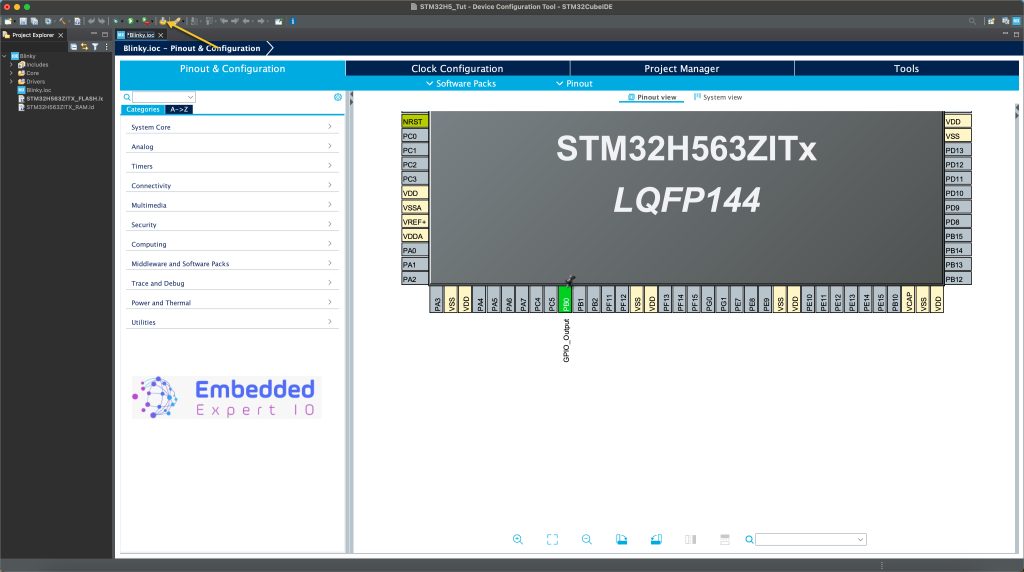
From the CubeIDE:
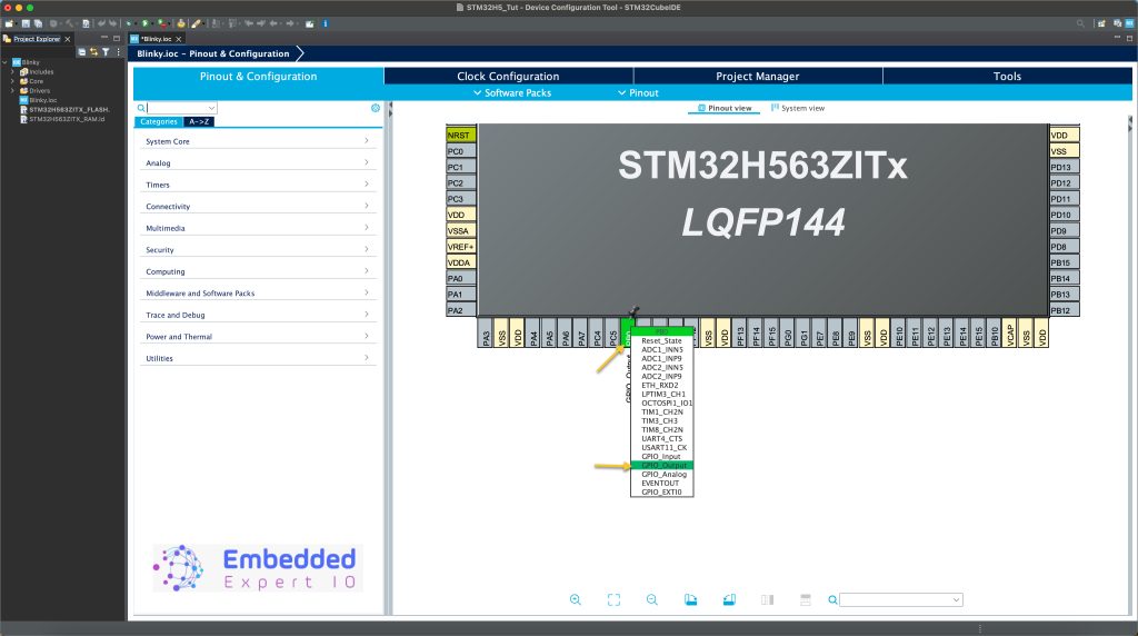
Select PB0 and set it as GPIO Output as shown.
Note: If this windows didn’t appear, click on blinky.ioc and it will appear.
Next click on generate code as following:
This will save the project and generate the code.
After that, the main.c will be opened.
In user code 3, which is in while 1 loop, we shall toggle the LED.
We have two options:
- HAL_GPIO_TogglePin(GPIOx, GPIO_Pin)
- HAL_GPIO_WritePin(GPIOx, GPIO_Pin, PinState)
The toggle function will toggle the state of the pin, if the pin is high, it will set it low and vise versa.
For the Write, it will set the pin to specific state either high or low.
Here, we shall use the write pin function.
In user code 3 in while loop, add the following:
	  HAL_GPIO_WritePin(GPIOB, GPIO_PIN_0, GPIO_PIN_SET);
	  HAL_Delay(500);
	  HAL_GPIO_WritePin(GPIOB, GPIO_PIN_0, GPIO_PIN_RESET);
	  HAL_Delay(500);
The write function will take the following parameters:
- GPIOx which is the GPIO port, GPIOB in this case.
- GPIO_Pin which is the pin number, GPIO_PIN_0 in this case.
- PinState, which is the state to be set, either Set to high or reset to low.
That all for the guide.
Save the project, build it and run it on your STM32H563Zi board.

4. Results:
Notice that the green LED is changing the state each half second as the code shows.
Happy coding 😉
2 Comments
hello, thank you for sharing
You are welcome
Add Comment