
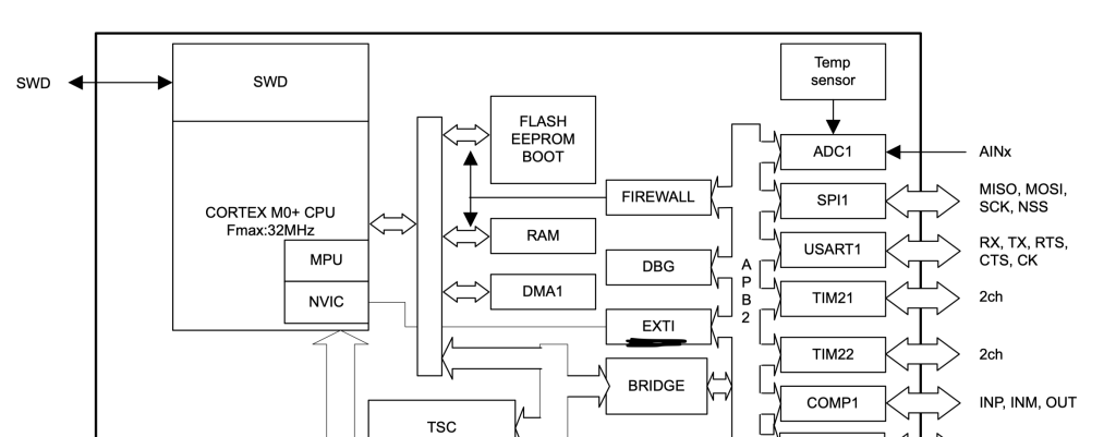
In this guide, we shall develop a driver for external interrupt in STM32L053-Nucleo-64 board.
In this guide, we shall cover the following:
- What is external interrupt.
- Developing external interrupt driver.
- Results.
1. What is External interrupt:
External Interrupts :
External interrupts come from input-output I/O devices.
Some examples that cause external interrupts:
- I/O devices requesting transfer of data
- I/O devices finished the transfer of data. When a program executes in an endless loop and thus exceeds its time limit, an external interrupt occurs which is Timeout Interrupt.
- While transferring the CPU’s complete state to a non-destructive memory in a few milliseconds before power ceases, then an external interrupt occurs.
Advantages of External Interrupts
- Increased Flexibility: External interrupts allow a system to respond to external events, such as a user input or an external sensor, in real-time. This can greatly improve the system’s flexibility, as it is not limited to a fixed operating cycle.
- Ability to Respond to External Events: External interrupts provide a mechanism for the system to respond to external events that may occur at any time. This allows the system to perform tasks in response to changes in the environment, such as user input or incoming data, without the need for continuous monitoring.
- Improved Performance and Efficiency: By allowing the system to respond to external events in real-time, external interrupts can greatly improve the system’s performance and efficiency, as it is not bogged down by continuous monitoring for changes.
Applications of External Interrupts
- Input Devices: External interrupts are commonly used in input devices, such as keyboards, mice, and touchpads, to respond to user input in real-time.
- Data Acquisition Systems: External interrupts can be used in data acquisition systems to respond to incoming data and process it in real-time.
- Robotics: External interrupts can be used in robotics systems to respond to external events, such as sensor inputs or user commands.
- Real-time Systems: External interrupts are commonly used in real-time systems, such as process control systems and medical equipment, to provide a mechanism for responding to external events in real-time.
2. Developing external interrupt driver:
Before we start developing the driver, we need to set the PC13 as input, please refer to this guide for how to set PC13 as input.
Also, we need PA5 as output which is connected to onboard LED, please refer to this guide.
We start of by enabling clock access to SYSCNFG as following:
	/*Enable clock access to sysconfig*/
	RCC->APB2ENR|=RCC_APB2ENR_SYSCFGEN;
We need to configure EXTI13 to be on portC as following:
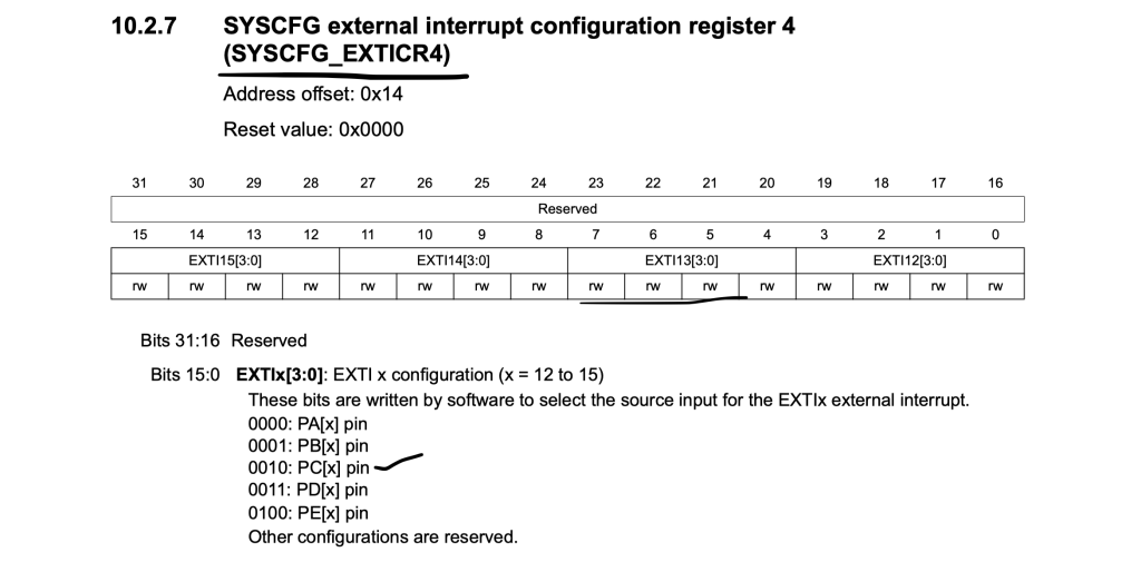
	/*Set EXTI13 to be on PORTC of GPIO*/
	SYSCFG->EXTICR[3]|=SYSCFG_EXTICR4_EXTI13_PC;
Unmask interrupt request from line 13 as following:
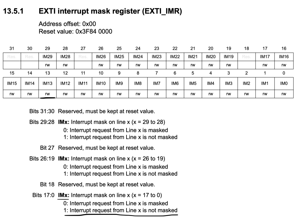
	/*Unmask Line 13*/
	EXTI->IMR|=EXTI_IMR_IM13;
Set the edge detection to be falling edge:
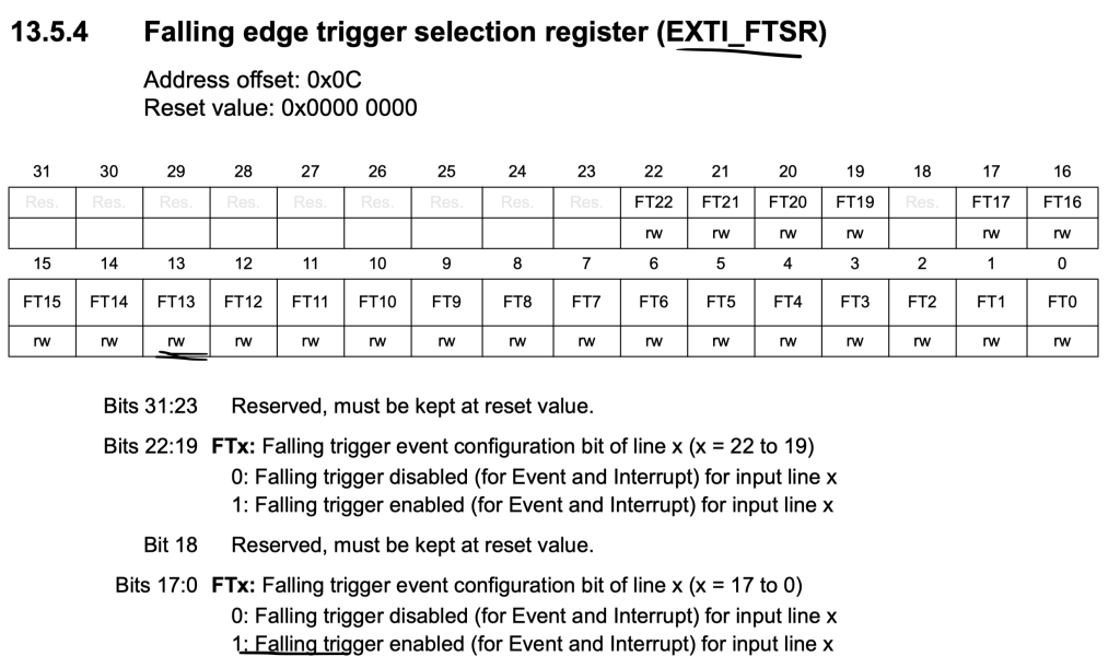
	/*Select falling edge detection*/
	EXTI->FTSR|=EXTI_FTSR_FT13;
Finally enable the EXTI13 in NVIC as following:
	/*Enable EXTI line in NVIC*/
	NVIC_EnableIRQ(EXTI4_15_IRQn);
Note that EXTI4 to EXTI15 share same interrupt line.
Within the interrupt handler:
Check if the source of the interrupt is line 13:
If it is line 13, clear the pending flag and toggle the LED.
void EXTI4_15_IRQHandler(void)
{

	/*Check if the interrupt source is line13*/
	if (EXTI->PR & EXTI_PR_PIF13)
	{
		/*Clear the pending flag*/
		EXTI->PR|=EXTI_PR_PIF13;

		/*Toggle the LED*/
		GPIOA->ODR^=GPIO_ODR_OD5;
	}
}
Hence, the entire code as following:
#include  "stm32l0xx.h"

int main(void)
{
	/*Enable clock access to GPIOA*/
	RCC->IOPENR |= RCC_IOPENR_GPIOAEN;
	/*Enable clock access to GPIOC*/
	RCC->IOPENR |= RCC_IOPENR_GPIOCEN;

	/*Set PA5 as output pin*/
	GPIOA->MODER |= GPIO_MODER_MODE5_0;
	GPIOA->MODER  &=~GPIO_MODER_MODE5_1;
	/* Set PC13 as input*/
	GPIOC->MODER&=~ GPIO_MODER_MODE13;

	/*Enable clock access to sysconfig*/
	RCC->APB2ENR|=RCC_APB2ENR_SYSCFGEN;

	/*Set EXTI13 to be on PORTC of GPIO*/
	SYSCFG->EXTICR[3]|=SYSCFG_EXTICR4_EXTI13_PC;

	/*Unmask Line 13*/
	EXTI->IMR|=EXTI_IMR_IM13;

	/*Select falling edge detection*/
	EXTI->FTSR|=EXTI_FTSR_FT13;

	/*Enable EXTI line in NVIC*/
	NVIC_EnableIRQ(EXTI4_15_IRQn);

	while(1)
	{

	}

}

void EXTI4_15_IRQHandler(void)
{

	/*Check if the interrupt source is line13*/
	if (EXTI->PR & EXTI_PR_PIF13)
	{
		/*Clear the pending flag*/
		EXTI->PR|=EXTI_PR_PIF13;

		/*Toggle the LED*/
		GPIOA->ODR^=GPIO_ODR_OD5;
	}
}
3. Results:
When you upload the code to your MCU and press the user button, you should see the LED toggle with each press as shown in this video:
Happy coding 🙂
Add Comment