Controlling a servo motor is a fundamental task in embedded systems, often used in robotics, automation, and mechatronics to achieve precise angular positioning. In this section, we will explore how to use an STM32 timer to generate the PWM signal required to drive a standard hobby servo motor.
In this guide, we shall cover the following:
- Introduction.
- Connection.
- STM32CubeIDE configuration.
- Firmware development.
- Results.
1. Introduction:
A servomotor is a rotary actuator or linear actuator that allows for precise control of angular or linear position, velocity and acceleration.[1] It consists of a suitable motor coupled to a sensor for position feedback. It also requires a relatively sophisticated controller, often a dedicated module designed specifically for use with servomotors. (Wikipedia link).
The servo motor used in our guide has three wires: red, brown and orange.
| Wire color | Function |
| Red | Vcc (4~6V) |
| Brown | GND |
| Orange | Signal |

1.2. Construction of Servo Motor:
The construction of the servo motor is shown in the figure below:
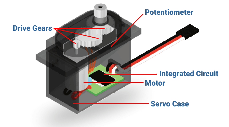
Typically, the servo motor is consist of the following parts:
- Drive great to decrease the rotation speed and increase the torque output of the motor.
- Feedback in form of potentiometer or encoder to get the current position of the putout shaft.
- Integrated circuit which compares the desired angle with the current angle and adjust the position accordingly.
- Motor which is responsible for the movement of the servo motor and it could be either DC or AC.
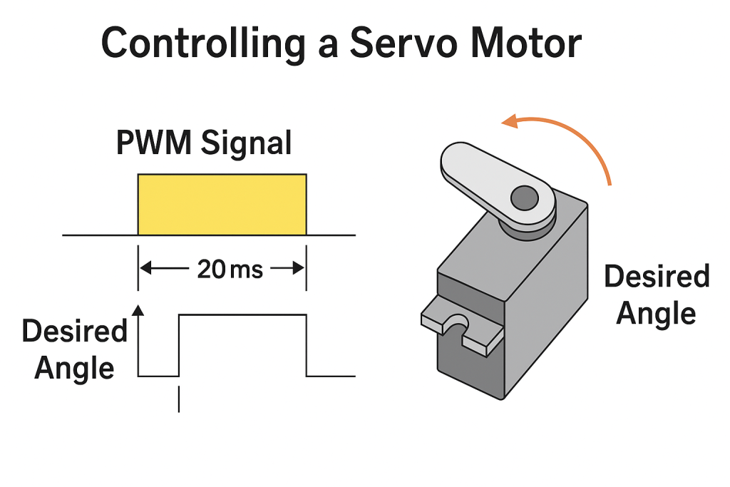
In order to control the angle of the servo motor, a PWM signal of frequency 50Hz (20mS period) needed to be applied to the signal pin on the servo motor. to determine the angle of the servo as following:
| Angle | Duty Cycle (Period) |
| 0 | 5% (1mS) |
| 90 | 7.5% (1.5mS) |
| 180 | 10%(2mS) |

However, in reality, the servo requires signal duration of 0.65ms for 0 position and 2.4ms for 180 degree position with frequency of 50Hz.
In this guide, we shall use DC version commonly used by RC vehicles and drones.
2. Connection:
In this guide, we need the following
- STM32F411 Nucleo
- SG90 microservo
- Hock-up wires
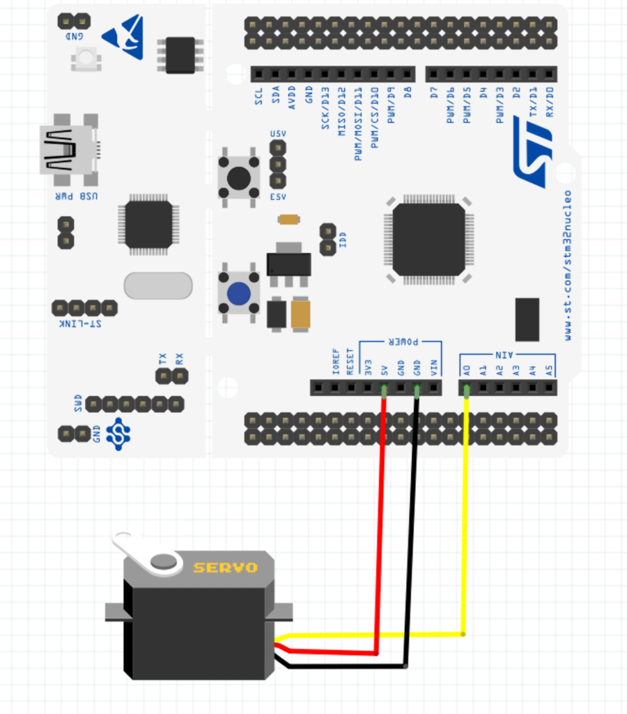
| Servo Motor | STM32F411 Nucleo-64 |
| Red | 5V |
| Brown | GND |
| Orange | PA0 |
3. STM32CubeIDE Configuration:
We shall setup timer in PWM. For how to configure timer in PWM mode, please refer to this guide here.
This guide shall continue from there.
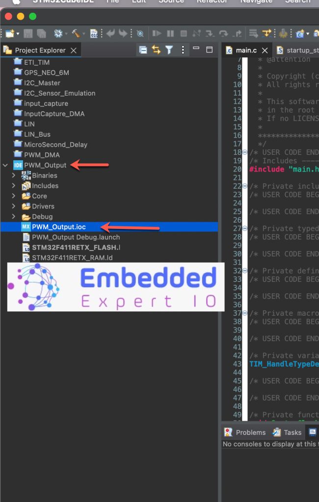
From the PWM guide, open .ioc file as follows:
Next, configure TIM2 as follows:
- Prescaler to 16-1.
- Counter Period to 20000-1.
- Pulse to 1000-1.
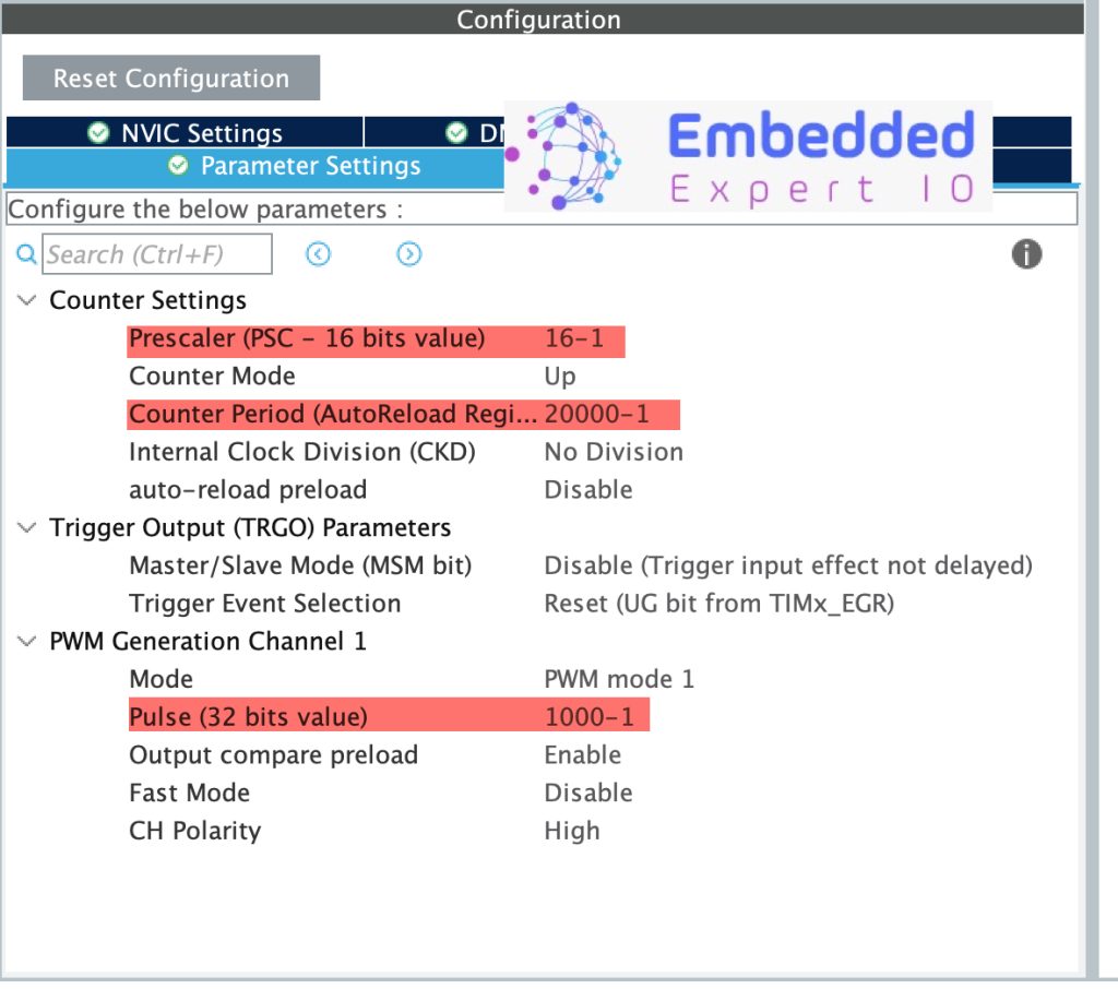
By this configuration, the timer shall generate 50Hz PWM signal which needed to control the servo. With Pulse width of 1000-1, the initial position will be 0.
Thats all for the STM32CubeIDE configuration. Save the project and the project shall be generated.
4. Firmware Development:
Once the project has been generated, the main.c file shall be open.
In main.c in user code begin 0, declare the following function:
int32_t map(int32_t x, int32_t in_min, int32_t in_max, int32_t out_min, int32_t out_max)
{
    return (x - in_min) * (out_max - out_min) / (in_max - in_min) + out_min;
}
This function will take a value of x, with minimum and maximum input output values and scale it according to the desired value.
Next, a function to control the servo angle as follows:
void servoAngle(uint16_t angle)
{
	if(angle>180)
	{
		angle=180;
	}

	// Map angle [0-180] to pulse [1000-2000]
	uint16_t pulse_length = map(angle, 0, 180, 900, 2500);

	__HAL_TIM_SET_COMPARE(&htim2, TIM_CHANNEL_1, pulse_length);
}
First, the function shall check if the angle is beyond 180 and set it to 180.
After that, convert the angle into duty cycle using the map function which declared previously and update the duty cycle of the PWM using __HAL_TIM_SET_COMPARE macro.
In user code begin 2 in main function, start the timer in PWM mode as follows:
HAL_TIM_PWM_Start(&htim2, TIM_CHANNEL_1);
In user code begin 3 in while loop, loop through all the angles as follows:
	  for (int i=0;i<180;i++)
	  {
		  servoAngle(i);
		  HAL_Delay(50);
	  }
	  for (int i=0;i<180;i++)
	  {
		  servoAngle(180-i);
		  HAL_Delay(50);
	  }
Thats all for the firmware, save the project, build and run it on your board as following:

5. Results:
Once you run you code and attach servo motor according to the connection, you should get the following:
Note: if you have bigger servo motor, you need to use external 5V power supply to provide power to the motor and connect a common ground between your MCU and power supply. (mine is small and not loaded and charger able to provide up to 3A)
Happy coding 😉
Add Comment