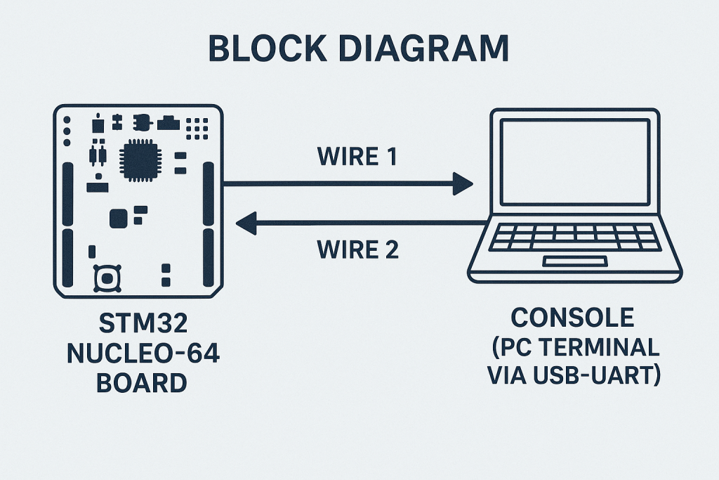
In this second part of our UART guide series, we will learn how to transmit data efficiently using interrupts and DMA.
These advanced methods free up CPU resources, enabling non-blocking communication for real-time embedded applications.
In this guide, we shall cover the following:
- Introduction and advantage of interrupt and DMA.
- STM32CubeIDE setup.
- Firmware development.
- Results.
1. Introduction and Advantage of Interrupt and DMA:
In embedded systems, efficient data transmission is critical to achieve real-time performance while minimizing CPU load. In Part 1 of this series, we explored UART configuration and basic data transmission using polling. While polling is simple and suitable for small or infrequent data transfers, it quickly becomes inefficient for high-speed communication or when multiple tasks need to run concurrently.
In this second part, we will delve into transmitting data using interrupts and DMA, two powerful techniques that overcome the limitations of polling by allowing the CPU to continue executing other tasks while data transmission occurs in the background.
Polling, Interrupt, and DMA – Detailed Comparison:
| Method | How it Works | Advantages | Disadvantages | Use Cases |
|---|---|---|---|---|
| Polling | The CPU actively checks the UART transmit flag in a loop, and sends data once the peripheral is ready. | Simple to implement and understand. Good for short, infrequent transmissions. | CPU is blocked during transmission, wasting cycles that could be used elsewhere. Inefficient for large or frequent transfers. | Debug print messages, initial bring-up tests, simple blocking communication. |
| Interrupt | Transmission is initiated, and the UART peripheral generates an interrupt when it is ready to send the next byte or when the transfer completes. The CPU executes an ISR to handle it. | Non-blocking – CPU can execute other code between interrupts. Suitable for medium-sized transfers. Flexible with moderate complexity. | Adds interrupt overhead; requires proper ISR implementation. Not ideal for large data streams where ISR latency can become significant. | Periodic data logging, sensor command-response protocols, real-time control loops. |
| DMA (Direct Memory Access) | The DMA controller transfers data directly from memory to UART peripheral without CPU intervention, only generating an interrupt on completion. | Fully non-blocking. CPU is completely free during data transfer. Ideal for large data transfers with minimal overhead. | Slightly more complex configuration. DMA availability may be limited based on other peripherals using it. | High-speed logging, streaming data (e.g. telemetry), large buffer transmissions, audio or video streaming. |
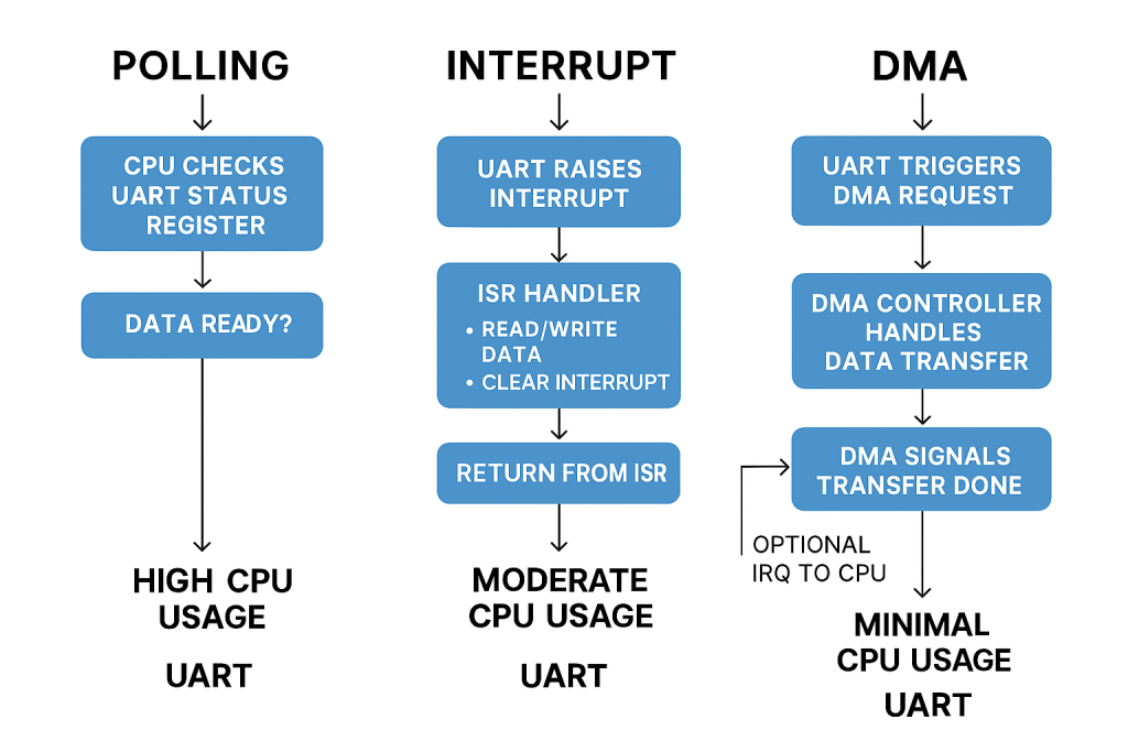
Using interrupt-based transmission allows the CPU to perform other tasks while small chunks of data are sent asynchronously. On the other hand, DMA-based transmission enables bulk data transfer with maximum efficiency, offloading the entire transfer process from the CPU. Understanding when to use each method is essential in embedded system design to achieve optimal performance and reliability.
In this part, we will configure UART transmission with interrupts and DMA on STM32, understand their implementation, and demonstrate their practical use cases for robust and efficient communication in your projects.
2. STM32CubeIDE Setup:
We shall continue from the previous guide here.
Once the CubeMX window appears, open UART2 as follows:
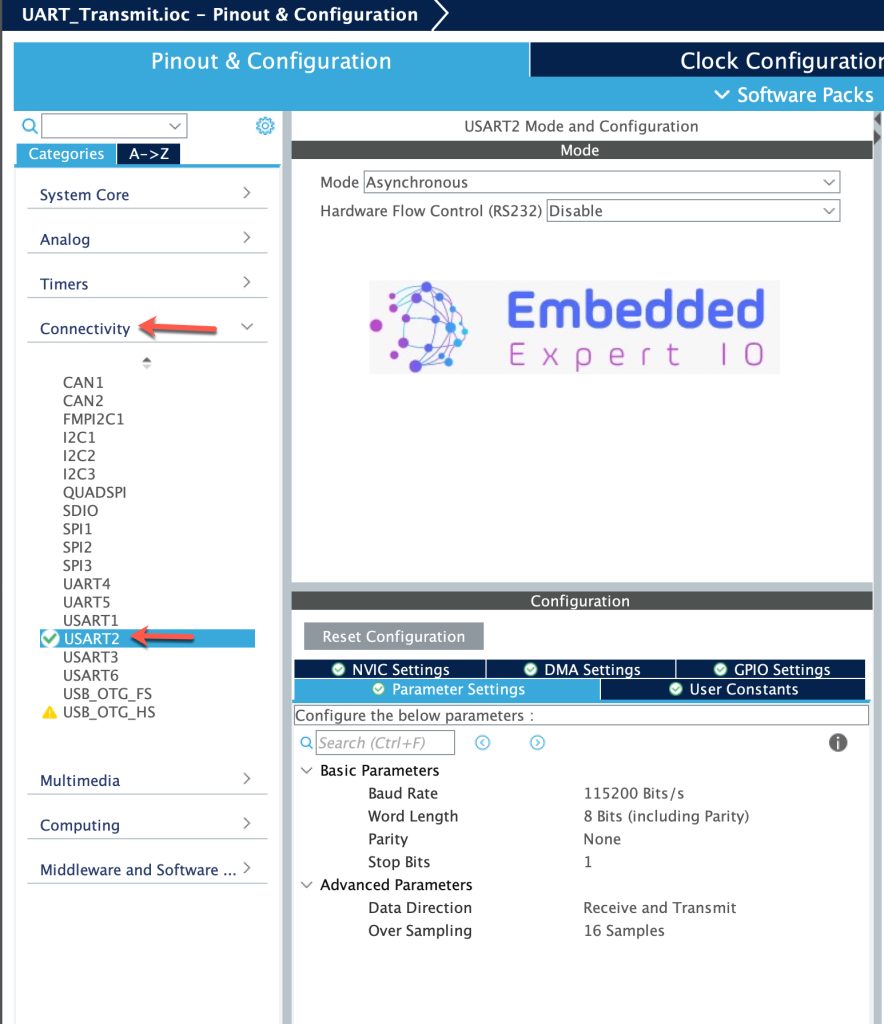
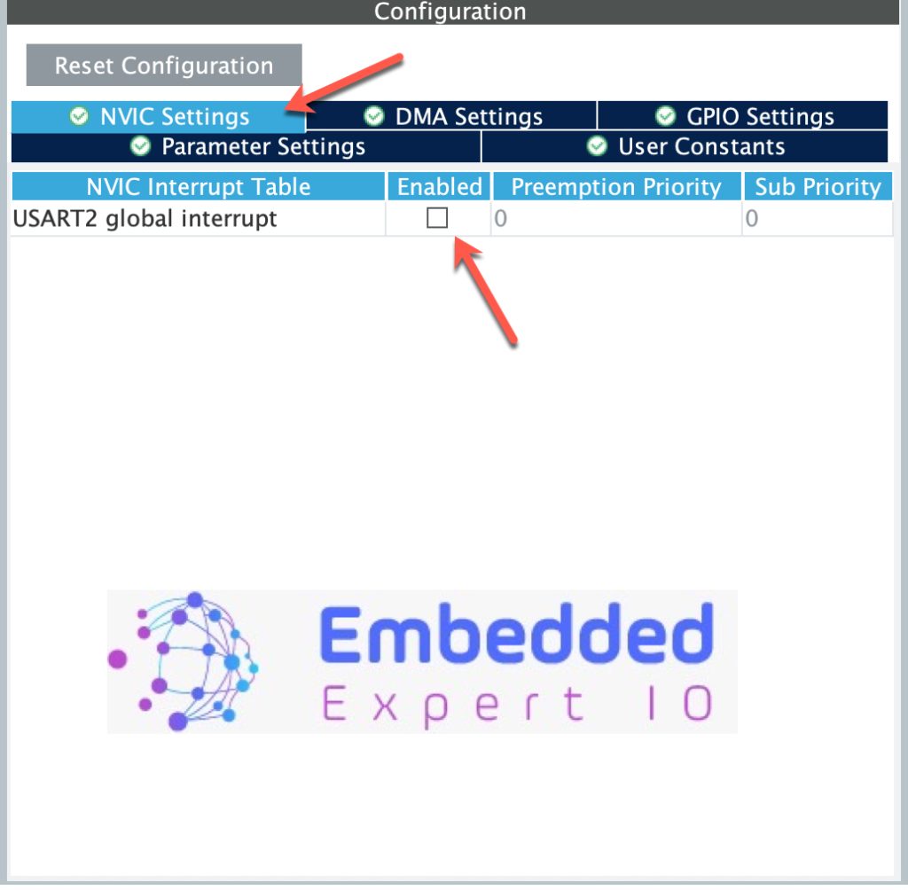
Next, from NVIC Settings, enable UART2 interrupts as follows:
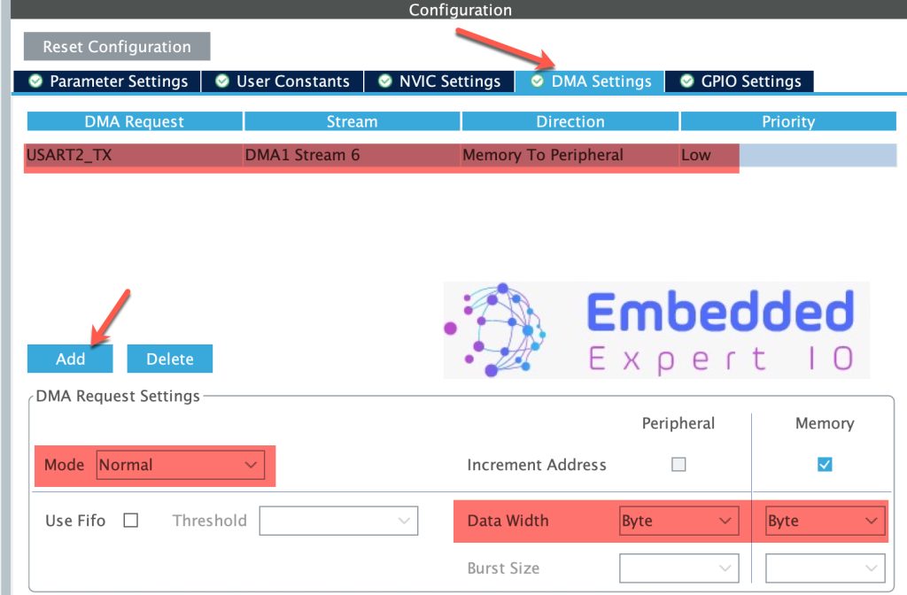
Next, from DMA Settings, add UART2_TX DMA as follows:
Thats all for the configuration. Save the project this will generate the project with updated parameters.
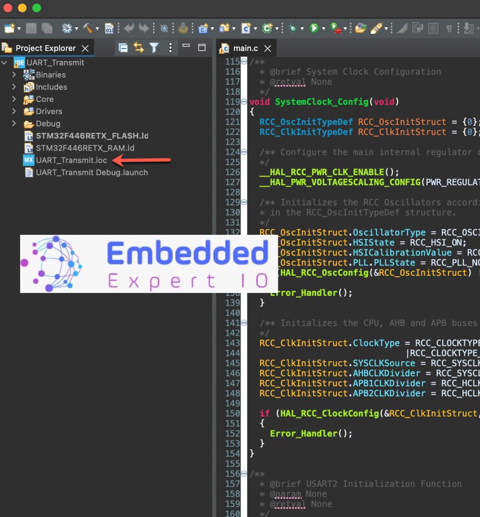
3. Firmware Development:
Once the project has been generated, main.c will be open.
In user code begin PV, declare the following volatile variable:
volatile uint8_t TxDone=0;
Once the the transfer is completed, the following function will called:
In user code begin 0:
void HAL_UART_TxCpltCallback(UART_HandleTypeDef *huart)
{
	if (huart->Instance==USART2)
	{
		TxDone=1;
	}
}
Function Purpose
HAL_UART_TxCpltCallback is a callback function provided by STM32 HAL library that is automatically called by the HAL driver when a UART transmission (Tx) is complete when using interrupt or DMA transmission functions such as:
HAL_UART_Transmit_IT()HAL_UART_Transmit_DMA()
Line-by-line breakdown
void HAL_UART_TxCpltCallback(UART_HandleTypeDef *huart)
Function definition:This is the user-implemented callback function with a pointer to the UART handle (huart) that triggered the callback.
if (huart->Instance == USART2)
huart->Instance points to the specific USART peripheral (e.g. USART1, USART2, etc.).This if condition ensures the callback only executes code for USART2 transmissions.Useful when your project uses multiple UARTs with different callback logic.
{
	TxDone = 1;
}
TxDone is a user-defined global or volatile variable acting as a flag to indicate transmission completion.Typically used in the main loop or other functions to know when it is safe to start a new transmission or perform actions dependent on Tx completion.
In user code begin 3:
uint16_t len=sprintf(uart_data,"Counter Value = %d\r\n",counter);

HAL_UART_Transmit_DMA(&huart2, uart_data, len);

while(TxDone==0);
TxDone=0;

HAL_UART_Transmit_IT(&huart2, uart_data, len);

while(TxDone==0);
TxDone=0;

counter++;

HAL_Delay(10);
HAL_UART_Transmit_DMA(&huart2, uart_data, len);
HAL_UART_Transmit_IT(&huart2, uart_data, len);
&huart2- Pointer to the UART handle structure for USART2.
- Contains all configuration and status information for this UART peripheral.
uart_data- Pointer to the data buffer you want to transmit.
- In this case, it is a character array containing your formatted string.
len- The length of data to transmit, in bytes.
- Ensures the DMA controller knows exactly how many bytes to transfer from memory to the UART data register.
uint16_t len = sprintf(uart_data, "Counter Value = %d\r\n", counter);- Formats a string with the current
countervalue. - Stores the formatted string in the
uart_databuffer. lenholds the length of the formatted string for transmission.
- Formats a string with the current
HAL_UART_Transmit_DMA(&huart2, uart_data, len);- Starts UART transmission using DMA on USART2.
- DMA transfers data directly from memory to the UART peripheral, freeing the CPU during transmission.
while (TxDone == 0);- Waits until DMA transmission completes.
TxDoneis set to 1 in theHAL_UART_TxCpltCallback()callback when transmission finishes.
TxDone = 0;- Resets the
TxDoneflag to prepare for the next transmission.
- Resets the
HAL_UART_Transmit_IT(&huart2, uart_data, len);- Starts UART transmission using interrupt on USART2.
- The UART peripheral sends data and triggers an interrupt when done.
while (TxDone == 0);- Waits until interrupt-based transmission completes.
- Again,
TxDoneis set in the transmit complete callback.
TxDone = 0;- Resets the flag after interrupt-based transmission for the next use.
counter++;- Increments the
countervariable for the next loop iteration.
- Increments the
HAL_Delay(10);- Adds a 10 ms delay before repeating the loop.
- Prevents sending data too rapidly.
Thats all for the firmware. Save the project and run it.
4. Results:
Using your favourite uart terminal and set the baud rate to 115200, you should get the following:
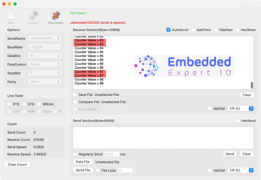
Noticed that the string is printed twice, once using DMA and the other using interrupt.
Now, you have functioning UART DMA/IT driver ready to be deployed.
Happy coding 😉
1 Comment
Thank you !
Add Comment