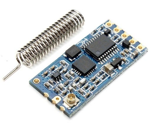
In the previous guide (here), we took a look at HC-12 RF module and setup the environment in STM32CubeIDE. In this guide, we shall continue the environment setup by initializing the user push button as external interrupt and library for HC-12.
In this guide, we shall cover the following:
- Enable User button as external interrupt.
- Developing the library.
- Code.
- Demo.
7. Enable user button as external interrupt:
To have deeper understand how to configure external interrupt for any GPIO, refer to this guide here.
Create new source and header file with name of exti.c and exti.h respectively.
Within header file:
#ifndef EXTI_H_
#define EXTI_H_
#include "stdint.h"

void PC13_EXTI_Init(void);
uint8_t button_Pressed();
void clear_pressed();


#endif /* EXTI_H_ */
Source file:
#include "exti.h"

#include "stm32f4xx.h"

volatile uint8_t pressed;


void PC13_EXTI_Init(void)
{
	/*Disable global interrupts*/
	__disable_irq();

	RCC->AHB1ENR |=RCC_AHB1ENR_GPIOCEN;

	GPIOC->MODER &= ~GPIO_MODER_MODE13;

	/*Enable clock access to syscnf*/

	RCC->APB2ENR|= RCC_APB2ENR_SYSCFGEN;

	/*Select PORTC for EXTI13*/
	SYSCFG->EXTICR[3] |= SYSCFG_EXTICR4_EXTI13_PC;

	/*Unmask EXTI13*/

	EXTI->IMR|=EXTI_IMR_IM13;

	/*Select falling edge*/

	EXTI->FTSR|= EXTI_FTSR_TR13;

	NVIC_EnableIRQ(EXTI15_10_IRQn);

	/*Enable global interrupts*/
	__enable_irq();
}

uint8_t button_Pressed()
{
	return pressed;
}

void clear_pressed()
{
	pressed=0;
}

void EXTI15_10_IRQHandler(void)
{
	if (EXTI->PR & EXTI_PR_PR13)
	{
		pressed=1;

		EXTI->PR|=EXTI_PR_PR13;
	}
}
Thats all for external interrupt.
8. Developing the library:
Now create new source and header file with name of hc_12.c and hc_12.h respectively.
Within the the header file, include the stdint as following:
#include "stdint.h"
Since there are multiple levels for power transmission, we can create enums for them as following:
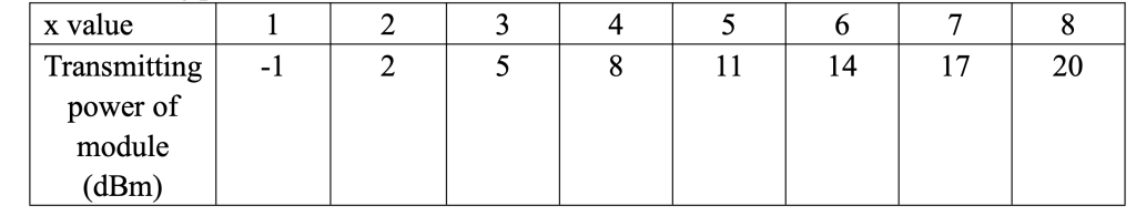
typedef enum
{
	P_Minus_1dBm =1,
	P_2dBm =2,
	P_5dBm =3,
	P_8dBm =4,
	P_11dBm =5,
	P_14dBm =6,
	P_17dBm =7,
	P_20dBm =8,
}HC_12_Power_Typedef;
There are ton of configuration for HC-12, but we are interested in three parameters:
- Buadrate.
- Channel.
- Power.
We can create data structure for the configuration as following:
typedef struct
{
	uint32_t Buadrate;
	uint8_t Channel;
	uint8_t Power;

}HC_12_Config_Typedef;
Also, we need the following two functions:
void HC_12_Config(HC_12_Config_Typedef *config);
void HC_12_SET_Pin_init(void);
First one to configure HC-12 and the second one initialize set pin.
Hence, the entire header file:
#ifndef HC_12_H_
#define HC_12_H_

#include "stdint.h"

typedef enum
{
	P_Minus_1dBm =1,
	P_2dBm =2,
	P_5dBm =3,
	P_8dBm =4,
	P_11dBm =5,
	P_14dBm =6,
	P_17dBm =7,
	P_20dBm =8,
}HC_12_Power_Typedef;

typedef struct
{
	uint32_t Buadrate;
	uint8_t Channel;
	uint8_t Power;

}HC_12_Config_Typedef;


void HC_12_Config(HC_12_Config_Typedef *config);
void HC_12_SET_Pin_init(void);


#endif /* HC_12_H_ */
Now, in the source file:
Include the following header files:
#include "hc_12.h"
#include "hc_12_uart.h"
#include "stdio.h"
#include "stm32f4xx.h"
#include "led.h"
Declare character array of 40 to hold AT commands to be send:
unsigned char at_data[40];
Volatile variable to store the received character:
volatile unsigned char uart1_rec;
Initializing the set pin function:
void HC_12_SET_Pin_init(void)
{
	RCC->AHB1ENR|=RCC_AHB1ENR_GPIOAEN;

	GPIOA->MODER|= GPIO_MODER_MODE0_0;

	GPIOA->MODER&= ~GPIO_MODER_MODE0_1;

	GPIOA->BSRR = GPIO_BSRR_BS0;

}
The configuration function:
void HC_12_Config(HC_12_Config_Typedef *config)
{
	GPIOA->BSRR = GPIO_BSRR_BR0;

	sprintf(at_data,"AT+B%d\r\n",config->Buadrate);
	hc12_write_at_command(at_data);

	if (config->Channel >127)
	{
		config->Channel=127;
	}

	if (config->Channel==0)
	{
		config->Channel=1;
	}

	sprintf(at_data,"AT+C%d\r\n",config->Channel);
	hc12_write_at_command(at_data);

	sprintf(at_data,"AT+P%d\r\n",config->Power);
	hc12_write_at_command(at_data);

	GPIOA->BSRR = GPIO_BSRR_BS0;

}
The function takes pointer to the structure of HC_12_Config_Typedef.
Within the function:
- Set set pin to low to enter AT mode.
- Set the baud rate to the desired baud rate.
- Set the channel from 1 to 27 with condition check.
- Set the power of transmitter.
- Set the set pin to high to exit the AT command.
Uart1 interrupt and callback function:
void HC_12_Callback(unsigned char ch)
{
	if (ch == '1')
	{
		led_toggle();
	}
}

void USART1_IRQHandler (void)
{

	if(USART1->SR & USART_SR_RXNE){
	uart1_rec=USART1->DR;
	HC_12_Callback(uart1_rec);

	USART1->SR &= ~USART_SR_RXNE;}


}
Within the callback function, we check if the received character is 1, if it is 1, toggle the LED.
Hence, the entire source file as following:
#include "hc_12.h"
#include "hc_12_uart.h"
#include "stdio.h"
#include "stm32f4xx.h"
#include "led.h"


unsigned char at_data[40];

volatile unsigned char uart1_rec;

void HC_12_SET_Pin_init(void)
{
	RCC->AHB1ENR|=RCC_AHB1ENR_GPIOAEN;

	GPIOA->MODER|= GPIO_MODER_MODE0_0;

	GPIOA->MODER&= ~GPIO_MODER_MODE0_1;

	GPIOA->BSRR = GPIO_BSRR_BS0;

}


void HC_12_Config(HC_12_Config_Typedef *config)
{
	GPIOA->BSRR = GPIO_BSRR_BR0;

	sprintf(at_data,"AT+B%d\r\n",config->Buadrate);
	hc12_write_at_command(at_data);

	if (config->Channel >127)
	{
		config->Channel=127;
	}

	if (config->Channel==0)
	{
		config->Channel=1;
	}

	sprintf(at_data,"AT+C%d\r\n",config->Channel);
	hc12_write_at_command(at_data);

	sprintf(at_data,"AT+P%d\r\n",config->Power);
	hc12_write_at_command(at_data);

	GPIOA->BSRR = GPIO_BSRR_BS0;

}


void HC_12_Callback(unsigned char ch)
{
	if (ch == '1')
	{
		led_toggle();
	}
}

void USART1_IRQHandler (void)
{

	if(USART1->SR & USART_SR_RXNE){
	uart1_rec=USART1->DR;
	HC_12_Callback(uart1_rec);

	USART1->SR &= ~USART_SR_RXNE;}


}
Also, we need to update the hc_12 serial with two functions:
- Send AT command:
void hc12_write_at_command(unsigned char * ch)
{
	while(*ch)
	{
		hc12_write_char(*ch);
		ch++;
	}
}- Send String:
void hc12_write_string(unsigned char * ch)
{
	while(*ch)
	{
		hc12_write_char(*ch);
		ch++;
	}
}
Hence the updated header file:
#ifndef HC_12_UART_H_
#define HC_12_UART_H_

#include "stdint.h"

void hc12_uart_init(uint32_t baud,uint32_t freq);

void hc12_write_char(unsigned char ch);

void hc12_write_at_command(unsigned char * ch);

void hc12_write_string(unsigned char * ch);


#endif /* HC_12_UART_H_ */
Within main.c:
Include the following header files:
#include "hc_12.h"
#include "hc_12_uart.h"
#include "led.h"
#include "time_base.h"
#include "exti.h"
declare the configuration structure as following:
HC_12_Config_Typedef hc12Config;
in main function:
Initialize everything:
	Ticks_Init(16000000);
	PC13_EXTI_Init();
	led_init();
	HC_12_SET_Pin_init();
	hc12_uart_init(9600, 16000000);
Configure HC-12:
	hc12Config.Buadrate=9600;
	hc12Config.Channel=1;
	hc12Config.Power=P_20dBm;
	HC_12_Config(&hc12Config);
In while 1 loop:
while(1)
	{
		if (button_Pressed())
		{
			clear_pressed();
			hc12_write_char('1');
		}
	}
Hence, the main.c as following:
#include "hc_12.h"
#include "hc_12_uart.h"
#include "led.h"
#include "time_base.h"
#include "exti.h"

HC_12_Config_Typedef hc12Config;

int main()
{

	Ticks_Init(16000000);
	PC13_EXTI_Init();
	led_init();
	HC_12_SET_Pin_init();
	hc12_uart_init(9600, 16000000);


	hc12Config.Buadrate=9600;
	hc12Config.Channel=1;
	hc12Config.Power=P_20dBm;
	HC_12_Config(&hc12Config);


	while(1)
	{
		if (button_Pressed())
		{
			clear_pressed();
			hc12_write_char('1');
		}
	}


}
9. Code:
You may download the entire source code from here:
10. Results:
Happy coding 🙂
Add Comment