In this guide, we shall take a look at HC-12 RF long range RF communication module.
In this guide, we shall cover the following:
- What is HC-12.
- Hardware setup.
- Serial Setup.
- LED setup.
- Time base.
- Code.
1. What is HC-12:
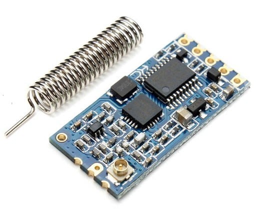
The HC-12 is a half-duplex 20 dBm (100 mW) transmitter paired with a receiver that has -117 dBm (2×10-15W) sensitivity at 5000 bps.
Paired with an external antenna, these transceivers are capable of communicating up to and possibly slightly beyond 1 km in the open and are more than adequate for providing coverage throughout a typical house.
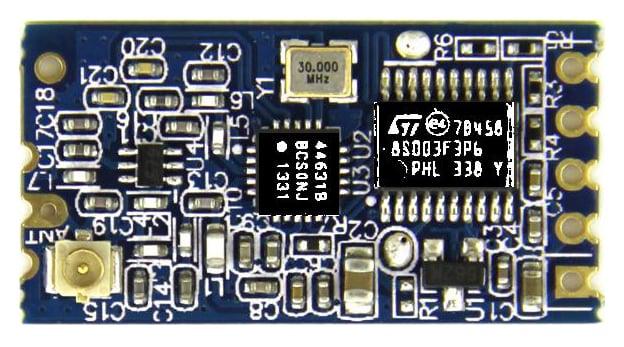
The HC-12 circuit board. Image courtesy of Seeed. This image has been digitally manipulated to enhance chip markings.
The HC-12 circuit board is built around the STM8S003F3 microcontroller and the Si4463 transceiver.
The Si4463 Transceiver
The Si4463 provides the wireless communication in this circuit. It has a maximum transmit power of 20 dBm (100 mW) and receive sensitivity of -129 dBm. Two 64-byte Rx and Tx FIFO memories are built into the chip along with a great many advanced features that are not implemented in the HC-12 design. See the datasheet for more information on multiband operation, frequency hopping, etc.
The STM8S003FS Microcontroller
This is an 8-bit microcontroller with 8 kB of flash memory, 128 bytes of EEPROM, and a 10-bit ADC. It supports UART, SPI, and I²C and has multiple I/O pins. It offers many of the same capabilities as its ATMega and XMC counterparts. It is programmed to control the Si4463 as well as handle the UART communication between the HC-12 and whatever it is connected to on the other end.
The HC-12 Transceiver Module
Combined with other components, the Si4463 and STM8S003 create the HC-12 transceiver, which provides a 4-pin TTL-level UART interface (Vcc, Gnd, Tx, Rx), with a 5th pin that is used to enter “command” mode for changing the module’s configuration. The HC-12 has 100 supported channels spaced 400 kHz apart, eight transmit levels, eight supported baud rates, and three different working modes.
The 5th pin on the HC-12 is labeled “Set” and, when driven to logic low, allows various settings to be selected on the HC-12 using AT commands sent to the “RXD” pin.
The default configuration of the HC-12 is FU3—on Channel 1, FU3 is a fully automatic and transparent (to other devices) setting that adapts to the transmission rate of the connected device (although 9600 baud is still required to program it in Command mode).
Note that as the transmission rate increases, the sensitivity of the receiver decreases. You can return to the default state by sending AT+DEFAULT once in command mode.
| Serial Port Baud Rate | Over-the-Air Baud Rate | Receiver Sensitivity |
|---|---|---|
| 1200 bps | 5000 bps | -117 dBm |
| 2400 bps | 5000 bps | -117 dBm |
| 4800 bps | 15000 bps | -112 dBm |
| 9600 bps | 15000 bps | -112 dBm |
| 19200 bps | 58000 bps | -107 dBm |
| 38400 bps | 58000 bps | -107 dBm |
| 57600 bps | 236000 bps | -100 dBm |
| 115200 bps | 236000 bps | -100 dBm |
2. Hardware setup:
In this guide, we need two STM32F4 and two HC-12 modules in order to make communication between both of the module:
The connection as following:
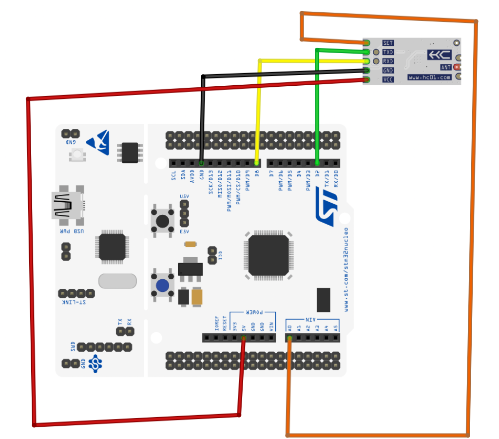
| STM32F44 | HC-12 Module |
| 5V | Vcc |
| GND | GND |
| PA9 (UART1_TX) | RX |
| PA10(UART1_RX) | TX |
| PA0 | Set |
Since this guide will use two Nucleo boards, we shall use the built-in LED to be controlled remotely.
3. Serial Setup:
We start off by creating new source and header file with name of hc_12_uart.c and hc_12_uart.h respectively.
Te utilitized UART is UART1 which will receive data using interrupt:
To see how to setup UART from scratch and everything related to it, please refer to this topic.
Within the header file:
#ifndef HC_12_UART_H_
#define HC_12_UART_H_

#include "stdint.h"

void hc12_uart_init(uint32_t baud,uint32_t freq);
void hc12_write_char(unsigned char ch);


#endif /* HC_12_UART_H_ */
Within the source file:
#include <hc_12_uart.h>
#include "stm32f4xx.h"


#define AF07 0x07


static void uart_set_baudrate(USART_TypeDef *USARTx, uint32_t PeriphClk,  uint32_t BaudRate);


void hc12_uart_init(uint32_t baud,uint32_t freq)
{
	/*Enable clock access to GPIOA and USART1*/
	RCC->APB2ENR|=RCC_APB2ENR_USART1EN;
	RCC->AHB1ENR|=RCC_AHB1ENR_GPIOAEN;
	/*Configure the GPIO for UART Mode*/
	GPIOA->MODER|=GPIO_MODER_MODE9_1;
	GPIOA->MODER&=~GPIO_MODER_MODE9_0;
	GPIOA->MODER|=GPIO_MODER_MODE10_1;
	GPIOA->MODER&=~GPIO_MODER_MODE10_0;
	GPIOA->AFR[1]|=(AF07<<GPIO_AFRH_AFSEL9_Pos)|(AF07<<GPIO_AFRH_AFSEL10_Pos); //ALT7 for UART1 (PA9 and PA10)
	/*Configure UART*/
	uart_set_baudrate(USART1,freq,baud);
	USART1->CR1|=USART_CR1_TE|USART_CR1_RE;
	USART1->CR1|=USART_CR1_RXNEIE;
	NVIC_EnableIRQ(USART1_IRQn);
	USART1->CR1|=USART_CR1_UE;
}

static uint16_t compute_uart_bd(uint32_t PeriphClk, uint32_t BaudRate)
{
	return ((PeriphClk + (BaudRate/2U))/BaudRate);
}

static void uart_set_baudrate(USART_TypeDef *USARTx, uint32_t PeriphClk,  uint32_t BaudRate)
{
	USARTx->BRR =  compute_uart_bd(PeriphClk,BaudRate);
}


void hc12_write_char(unsigned char ch)
{
	/*Make sure the transmit data register is empty*/
	while(!(USART1->SR & USART_SR_TXE)){}

	/*Write to transmit data register*/
	USART1->DR  =  (ch & 0xFF);
}
The interrupt handler shall be handled in part 2.
4. LED setup:
Since the built-in LED is connected to PA5, we need to configure PA5 as output:
For more details, please refer to this topic.
create new source and header file with name of led.c and led.h respectively.
Within header file:
#ifndef LED_H_
#define LED_H_

void led_init(void);
void led_on(void);
void led_off(void);
void led_toggle(void);
Within source file:
#include "led.h"
#include "stm32f4xx.h"


void led_init(void)
{
	RCC->AHB1ENR|=RCC_AHB1ENR_GPIOAEN;
	GPIOA->MODER|=GPIO_MODER_MODE5_0;
	GPIOA->MODER&=~GPIO_MODER_MODE5_1;

}

void led_on(void)
{
	GPIOA->BSRR=GPIO_BSRR_BS5;
}

void led_off(void)
{
	GPIOA->BSRR=GPIO_BSRR_BR5;
}

void led_toggle(void)
{
	GPIOA->ODR^=GPIO_ODR_OD5;
}
5. Time Base setup:
To see how to implement time base from scratch, please refer to this topic.
Within the header file:
#ifndef TIME_BASE_H_
#define TIME_BASE_H_

#include "stdint.h"

void Ticks_Init(uint32_t freq);
uint32_t get_Ticks();
void delay(uint32_t delay_ms);
Source code:
#include "time_base.h"

#include "stm32f4xx.h"


volatile uint32_t current_ticks;

void Ticks_Init(uint32_t freq)
{
	/*Load the SysTick value to be the core frequency over 1000
	 *
	 * Since th core frequency is in MHz, dividing it by 1000 will get 1ms period
	 * */
	SysTick->LOAD=(freq/1000)-1;

	/*Set the source to be internal core clock*/
	SysTick->CTRL=(1<<SysTick_CTRL_CLKSOURCE_Pos);

	/*Enable The interrupt */

	SysTick->CTRL|=(1<<SysTick_CTRL_TICKINT_Pos);

	/*Enable Systick Interrupt in NIVC*/

	NVIC_EnableIRQ(SysTick_IRQn);

	/*Enable Systick*/
	SysTick->CTRL|=(1<<SysTick_CTRL_ENABLE_Pos);


}

void SysTick_Handler()
{
	/*Increment the counter*/
	current_ticks++;
}

uint32_t get_Ticks()
{
	/*Return the counter value*/
	return current_ticks;
}

/*Spin lock the CPU to force delay*/
void delay(uint32_t delay_ms)
{

	uint32_t ticks_start=get_Ticks();

	while(get_Ticks()-ticks_start<delay_ms);
}
6. Code:
You may download the environment from here:
In part 2, we shall initialize the HC-12 and start controlling the LED.
Stay tuned.
Happy coding 🙂
Add Comment