
In the previous guide (here), we took a look how to use ADC in DMA mode to acquire the data from two channels. In this guide, we shall see how to configure the ADC to be triggered by timer.
In this guide, we shall cove the following:
- Timer triggered ADC with DMA.
- Connection.
- Code.
- Results:
1. Timer triggered ADC with DMA:
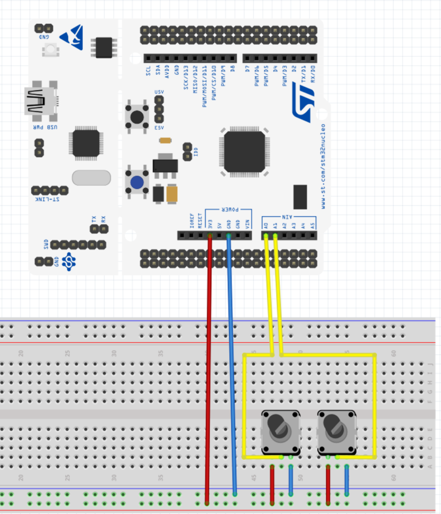
We start off by enabling clock access to port A and set PA0 and PA1 to analog mode:
	/****Configure gpio pin for adc***/
	/*Enable clock access to GPIOA*/
	RCC->IOPENR |=RCC_IOPENR_IOPAEN;

	/*Set pa4 mode to analog mode*/
	GPIOA->MODER |=GPIO_MODER_MODE0|GPIO_MODER_MODE1;
Enable clock access to ADC1:
	/*Enable clock access to ADC*/
	RCC->APB2ENR |= RCC_APB2ENR_ADC1EN;
Select hardware trigger detection on rising edge from ADC configuration register 1:
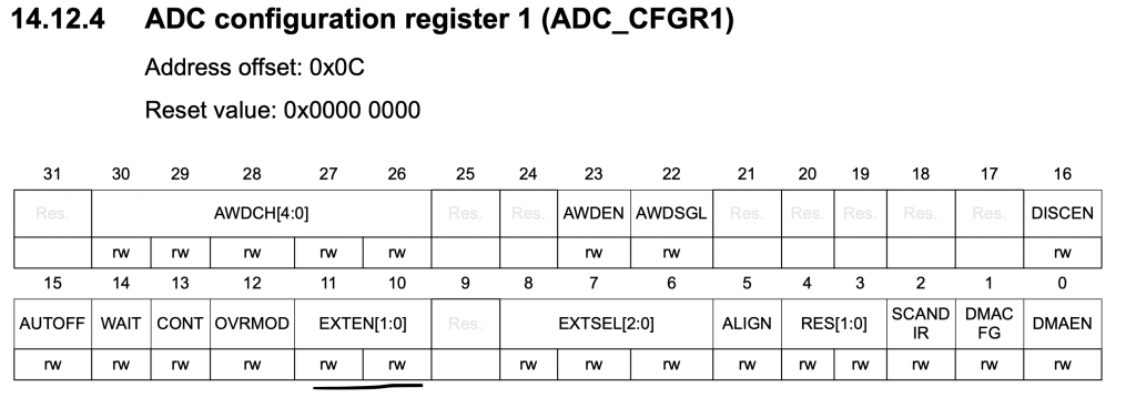
	/*Enable external trigger on rising edge*/
	ADC1->CFGR1|=ADC_CFGR1_EXTEN_0;
Select TRG2 as source for the trigger of the ADC1:
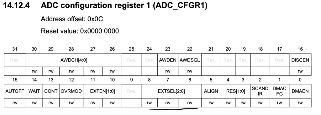
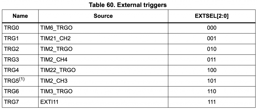
	/*Select TRG2 (TIM2_TRGO)*/
	ADC1->CFGR1|=ADC_CFGR1_EXTSEL_1;
Set sequencer channel to be channel 0 and channel 1:
	/*Set sequencer channel*/
	ADC1->CHSELR |=ADC_CHSELR_CHSEL0|ADC_CHSELR_CHSEL1;
Set the clock to be CLK/2:
	/*Set clock to be CLCK/2*/

	ADC1->CFGR2|=ADC_CFGR2_CKMODE_0;
Now enable clock access to TIM2:
	/*Enable clock access to TIM2*/
	RCC->APB1ENR|=RCC_APB1ENR_TIM2EN;
In master mode selection in CR2 register of TIM2, set the mode to be update:
TIM2->CR2|=TIM_CR2_MMS_1;
Set the PSC and ARR to the desired rate (1Hz in this guide ):
	TIM2->PSC=2097;
	TIM2->ARR=1000;
For the DMA configuration, it is similar to the previous guide with addition in interrupt generation when transfer is completed:
RCC->AHBENR|=RCC_AHBENR_DMA1EN;
	DMA1_Channel1->CCR|=DMA_CCR_MSIZE_0|DMA_CCR_PSIZE_0|DMA_CCR_MINC|DMA_CCR_CIRC|DMA_CCR_TCIE;
	NVIC_EnableIRQ(DMA1_Channel1_IRQn);
	DMA1_Channel1->CNDTR=sizeof(adc_dma_data)/sizeof(adc_dma_data[0]);
	DMA1_Channel1->CPAR= (uint32_t)(&ADC1->DR);
	DMA1_Channel1->CMAR=(uint32_t)(&adc_dma_data);
	DMA1_Channel1->CCR|=DMA_CCR_EN;
The reset of ADC configuration is similar:
	ADC1->CFGR1|=ADC_CFGR1_DMACFG;
	ADC1->CR |= ADC_CR_ADCAL;
	while(ADC1->CR & ADC_CR_ADCAL);
	ADC1->CR |= ADC_CR_ADEN;
	/*Start conversion*/
	ADC1->CR |= ADC_CR_ADSTART;
Finally enable the timer:
	/*Enable TIM2*/
	TIM2->CR1|=TIM_CR1_CEN;
For the interrupt handler:
volatile uint8_t done;
void DMA1_Channel1_IRQHandler (void)
	{
		if(DMA1->ISR & DMA_ISR_TCIF1)
			{
				done=1;
				DMA1->IFCR|=DMA_IFCR_CTCIF1;

			}

	}
In the main.c file:
#include "uart.h"
#include "adc.h"
#include "stdio.h"
extern volatile uint8_t done;
int main(void)
{
adc_dma_tim_init();
uart_init();
while(1)
{
if (done==1)
{
done=0;
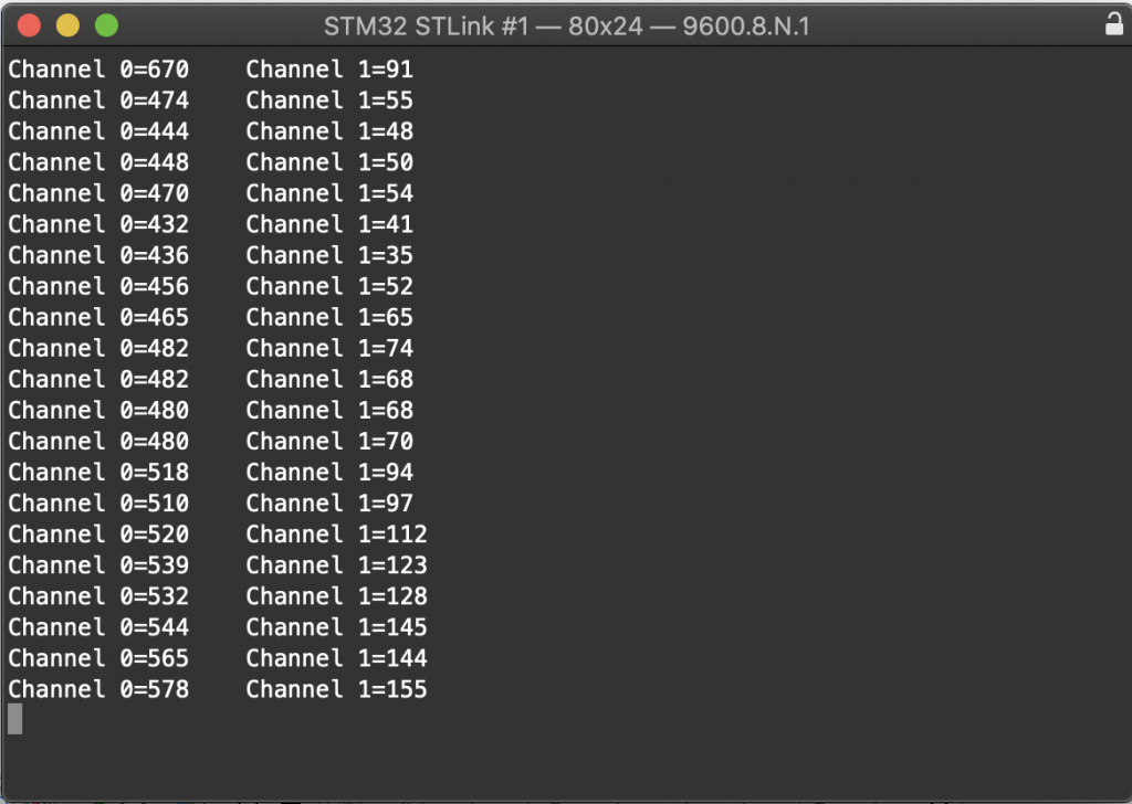
printf("Channel 0=%d\t Channel 1=%d\r\n",get_adc_value(Channel0),get_adc_value(Channel1));
}
}
}
2. Connection:
3. Code:
You may download the code from here:
4. Results:
Open your favourite terminal and set the baudrate to 9600 and you will notice it will be update the value each second.
Happy coding 🙂
Add Comment