As you may know memory holds code and data for the CPU to process ,and the I/ O ports are used by the CPU to access input and output devices.
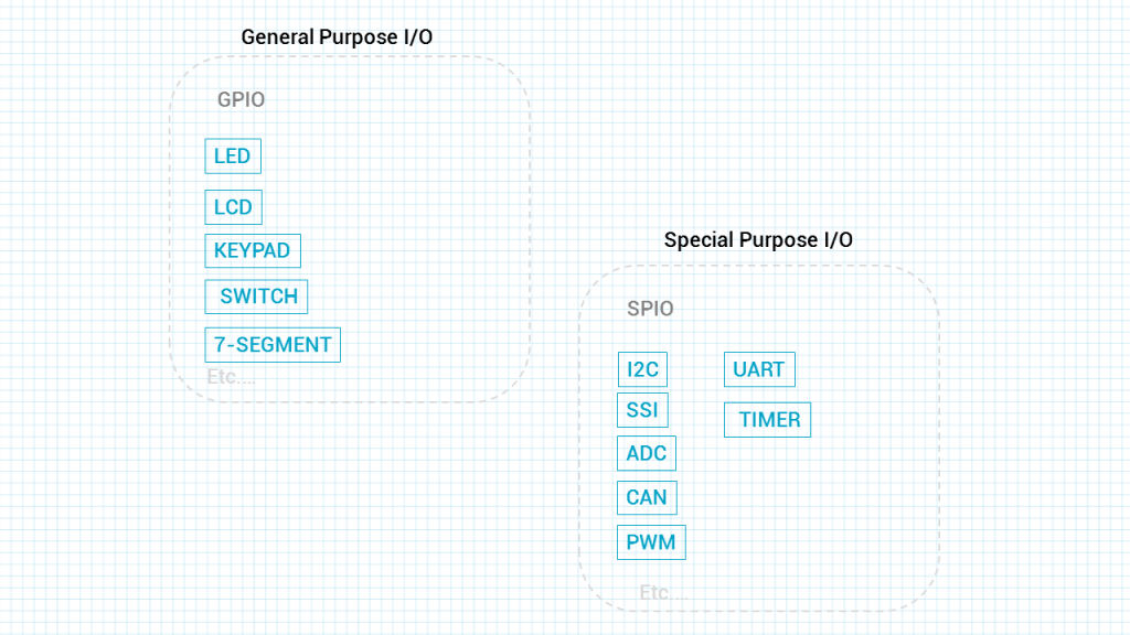
In the microcontroller we have two types of I/ O. They are: a. General Purpose I/ O (GPIO): The GPIO ports are used for interfacing devices such as LEDs, switches, LCD, keypad, and so on. b. Special purpose I/ O: These I/ O ports have designated function such as ADC (Analog-to-Digital), Timer, UART (universal asynchronous receiver transmitter), and so on.
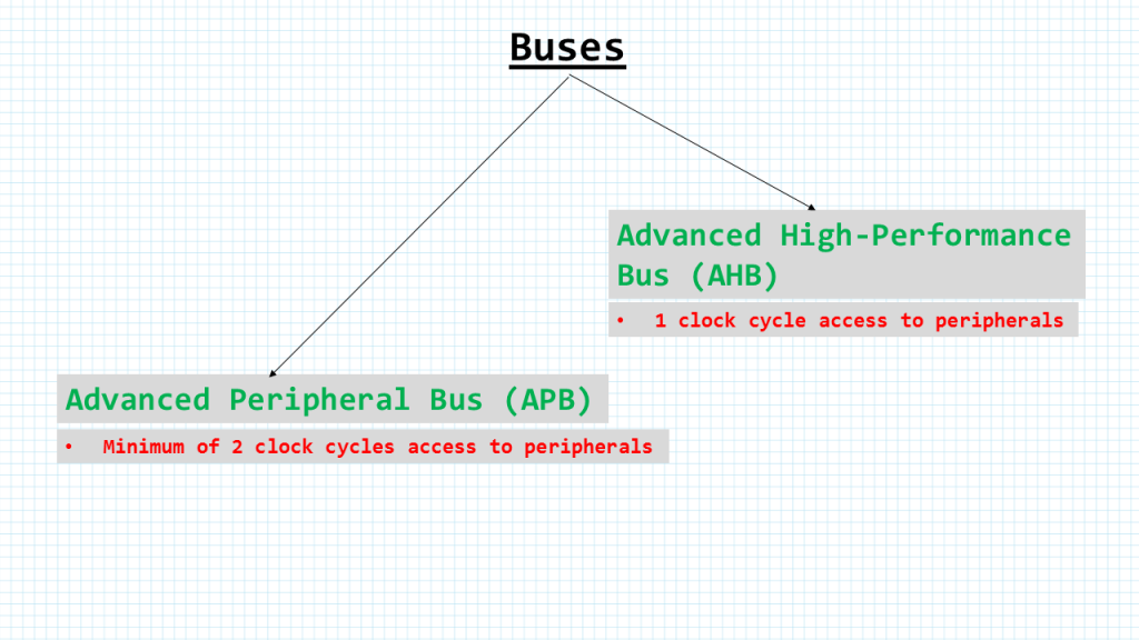
Buses
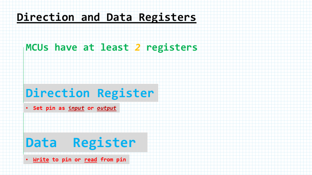
Direction and Data registers
Every microcontroller has a minimum of two registers for io control. The keyword here is minimum. We we go to program our mcu we need setup at least 3 or 4 registers depending on the mcu we are using. The to minimum required registers are the data register and the direction register. The Direction register is used to make the pin either input or output.
After the Direction register is properly set up, then we use the Data register to actually write to the pin or read data from the pin.
STM32F411-NUCLEO LED BLINK
#include "stm32f4xx.h"

void delayMs(int n);

int main(void) {
    RCC->AHB1ENR |=  1;             /* enable GPIOA clock */

    GPIOA->MODER &= ~0x00000C00;
    GPIOA->MODER |=  0x00000400;

    while(1) {
        GPIOA->ODR |=  0x00000020;
        delayMs(500);
        GPIOA->ODR &= ~0x00000020;
        delayMs(500);
    }
}

/* Psuedo delay based on Keil uVision compiler and  16 MHz SYSCLK */
void delayMs(int n) {
    int i;
    for (; n > 0; n--)
        for (i = 0; i < 3195; i++) ;
}
STM32F411-NUCLEO INPUT/OUTPUT
#include "stm32f4xx.h"

int main(void) {
    RCC->AHB1ENR |=  4;
    RCC->AHB1ENR |=  1;

    GPIOA->MODER &= ~0x00000C00;
    GPIOA->MODER |=  0x00000400;

    GPIOC->MODER &= ~0x0C000000;

    while(1) {
        if (GPIOC->IDR & 0x2000)        /* if PC13 is high */
            GPIOA->BSRR = 0x00200000;   /* turn off green LED */
        else
            GPIOA->BSRR = 0x00000020;   /* turn on green LED */
    }
}
1 Comment
This code is wonderfully clean!
As in other stm32 articles. Compared to what stm32Cube generates.
How do you compile this code (for STM32F411RE on Nucleo-64) board on Windows?
Tool-chain?
Add Comment