In this fourth part of the STM32 ADC series, we focus on using interrupts and DMA to efficiently read multiple ADC channels in scan mode. These techniques allow seamless, non-blocking acquisition of multi-channel analog data, significantly reducing CPU load while ensuring timely and reliable data collection.
In this guide, we shall cover:
- Interrupt vs DMA.
- STM32CubeMX setup.
- Firmware Development.
- Results.
1. Interrupt VS DMA:
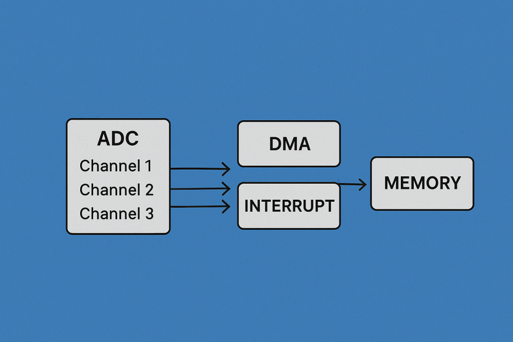
When implementing ADC (Analog-to-Digital Converter) functionality in STM32 microcontrollers, especially for reading multiple channels or acquiring high-speed signals, selecting between DMA (Direct Memory Access) and Interruptmodes is a critical architectural decision. Each approach has its own benefits, limitations, and ideal scenarios. This section breaks down both methods extensively.
❖ 1. Overview
| Aspect | DMA | Interrupt |
|---|---|---|
| Mechanism | Transfers ADC data directly to memory without CPU involvement. | ADC conversion completion triggers an ISR (Interrupt Service Routine). |
| CPU Involvement | Minimal or none | Moderate (CPU executes ISR) |
| Speed/Efficiency | High-speed, suitable for large or continuous data | Moderate speed; overhead increases with more channels or higher sample rate |
| Complexity | Medium (initial setup, but very efficient later) | Low to medium (depends on logic in ISR) |
❖ 2. DMA (Direct Memory Access)
✅ Advantages:
- Non-blocking: Frees the CPU to perform other tasks while data is being transferred.
- High Throughput: Ideal for high-speed sampling or when reading multiple ADC channels rapidly.
- Efficient Buffering: Allows use of circular buffers for continuous acquisition (great for real-time systems).
- Lower Latency: Faster transfer from ADC data register to memory.
❌ Disadvantages:
- More Complex Setup: Requires configuring the DMA controller, ADC, and sometimes a timer trigger.
- Debugging Difficulty: Errors are harder to debug compared to simple polling or interrupt routines.
- Fixed Transfer Size: Predefined buffer sizes must be used, although circular mode helps mitigate this.
- Memory Bound: DMA uses RAM, so buffer sizes must be carefully managed in memory-limited systems.
✅ Best Use Cases:
- High-speed sampling (audio, vibration, high-rate sensors).
- Real-time systems needing minimal CPU interruption.
- Acquisition from multiple channels with predictable sampling timing.
❖ 3. Interrupt Method
✅ Advantages:
- Simple to Implement: Suitable for beginners or low-speed applications.
- Flexible Logic: Custom post-processing logic (e.g., filtering, calibration) can be executed immediately in the ISR.
- Low Resource Requirement: Does not require special peripheral like DMA; uses standard interrupt controller.
❌ Disadvantages:
- CPU Overhead: Each ADC conversion triggers an interrupt, causing increased context switching.
- ISR Latency: If multiple channels or fast sampling is involved, ISR delay may lead to missed conversions.
- Blocking Risk: If ADC interrupt is not prioritized properly, it can lead to delays in critical tasks.
✅ Best Use Cases:
- Low-frequency or event-driven ADC sampling.
- Applications requiring immediate, small-scale post-processing.
- Prototyping and learning ADC fundamentals.
❖ 4. Performance Comparison (Example Case)
| Scenario | DMA | Interrupt |
|---|---|---|
| 3 Channels @ 10kHz Sample Rate | ✅ Efficient, handles easily | ⚠️ CPU load increases, ISR stack grows |
| Single Channel @ 500Hz | ⚠️ Overkill | ✅ Simple and effective |
| Real-time control loop (e.g., PID) | ✅ Precise timing with Timer + DMA | ⚠️ ISR jitter may affect stability |
❖ 5. Combined Use (DMA + Interrupt)
For advanced cases, DMA and Interrupt can be combined:
- DMA handles the transfer, and an interrupt is triggered at the end of transfer (EOT).
- Useful for batch processing or when memory buffers need to be processed after being filled.
2. STM32CubeMX Setup:
From the setup of the previous guide from here.
Open.ioc file and STM32CubeMX window shall appear.
From left side menu, Analog and select ADC1 as following:
Enable IN1, IN2 and IN4 as single ended input (Not all STM32 has this feature).
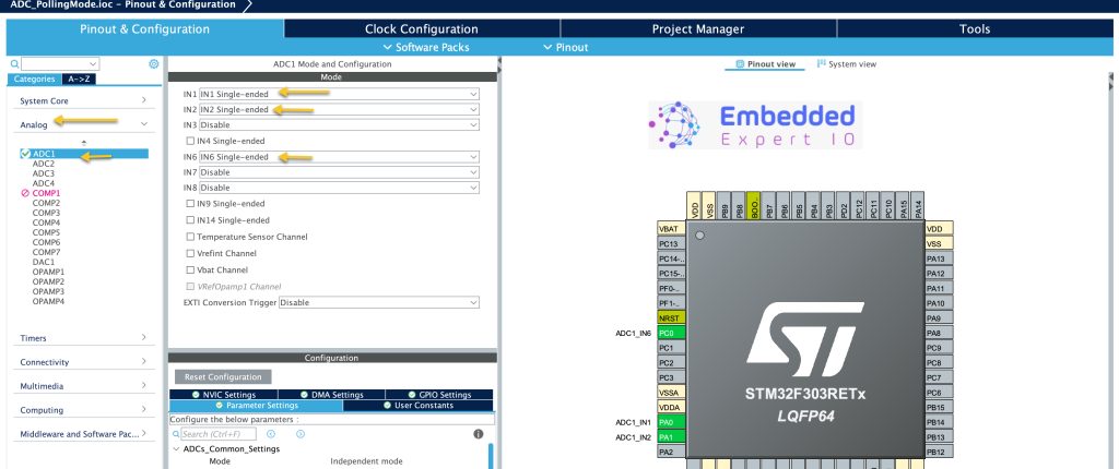
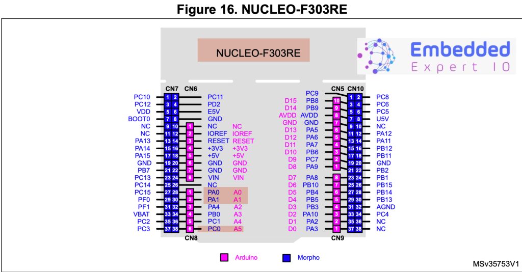
This will translate to A0, A1 and A5 analog pins of Arduino in STM32F303RE Nucleo-64:
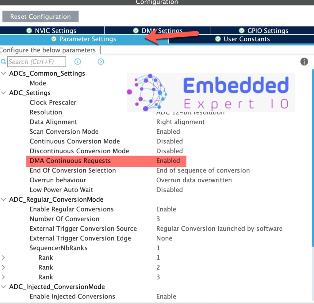
Next, we shall configure the ADC as following:
- First, set Number of Conversion to 3, this will enable Scan Conversion Mode
- Set end of Conversion Selection to End of sequence of conversion.
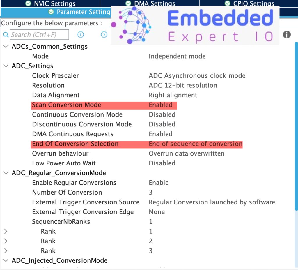
Next, set the rand of the channels as follows:
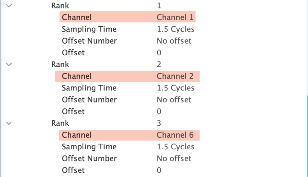
By setting the rank as shown, the conversion sequence shall be like this:
- Channel 1.
- Channel 2.
- Channel 6.
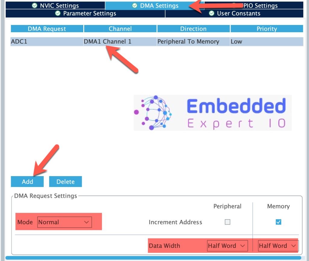
Next, from DMA, enable DMA as follows:
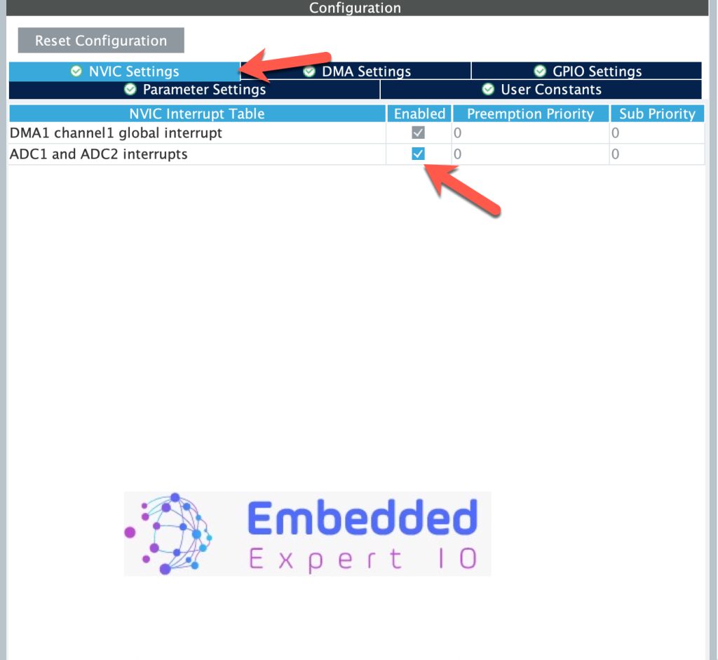
Next, from NVIC, enable ADC interrupt as follows:
From parameters settings, enable DMA continuous request as follows:
Thats all for the STM32CubeMX setup.
Save the project and the project shall be generated.
3. Firmware Development:
Once the project has been generated, main.c shall be opened.
3.1 Interrupt Method
In main.c, start by declaring the following:
In user code begin PV:
#define ADC_Size 3
uint16_t adcValue[ADC_Size];
This array shall hold the converted ADC data.
Next, in user code begin 2, in main function, start the ADC in the interrupt mode as follows:
HAL_ADC_Start_IT(&hadc1);
Once the ADC completed the conversion, the ADC conversion completed callback shall be called as follows:
void HAL_ADC_ConvCpltCallback(ADC_HandleTypeDef* hadc)
{
	if(hadc->Instance==ADC1)
    {
    	for (int i=0;i<ADC_Size;i++)
		{
			adcValue[i]=HAL_ADC_GetValue(hadc);
		}
		HAL_ADC_Start_IT(hadc);
    }
In the function, check if the interrupt source is ADC1, if it is, read all the channels and start the ADC in the interrupt mode again.
Notice that we are forced to read the data using for loop which is inefficient at all.
3.2 DMA Method:
In user code begin 2 in main function, start the ADC in DMA as follows:
HAL_ADC_Start_DMA(&hadc1, &adcValue, 3);
The function shall start the ADC in DMA mode and takes the following parameters:
- Instant to the ADC which is hadc1.
- Address of the array that holds the adc converted data.
- Size of the conversion which is 3.
Once the ADC completed the conversion, adc conversion completed callback shall be called:
void HAL_ADC_ConvCpltCallback(ADC_HandleTypeDef* hadc)
{
 	if(hadc->Instance==ADC1)
    {
    	HAL_ADC_Start_DMA(hadc, adcValue, 3);
    }
}
Similar to interrupt method, rather than reading the adc converted data manually, DMA handled that in the background.
In the interrupt check the interrupt source and if it ADC1, start the ADC again.
Thats all for the guide.
4. Results:
Start the debug session and add adcValue to Live Expression and you should get the following:
Next, we shall cover the continuous mode using DMA and interrupt, stay tuned.
Happy coding 😉
Add Comment