Input Capture Mode in STM32 allows precise measurement of the time between signal edges by capturing timer counter values. It is commonly used for measuring signal period, pulse width, or event timing in embedded applications.
In this guide, we shall cover the following:
- What is input capture and its application.
- STM32CubeIDE setup.
- Connection.
- Firmware development.
- Results.
1. What is Input capture and its Application:
What is Input Capture in STM32?
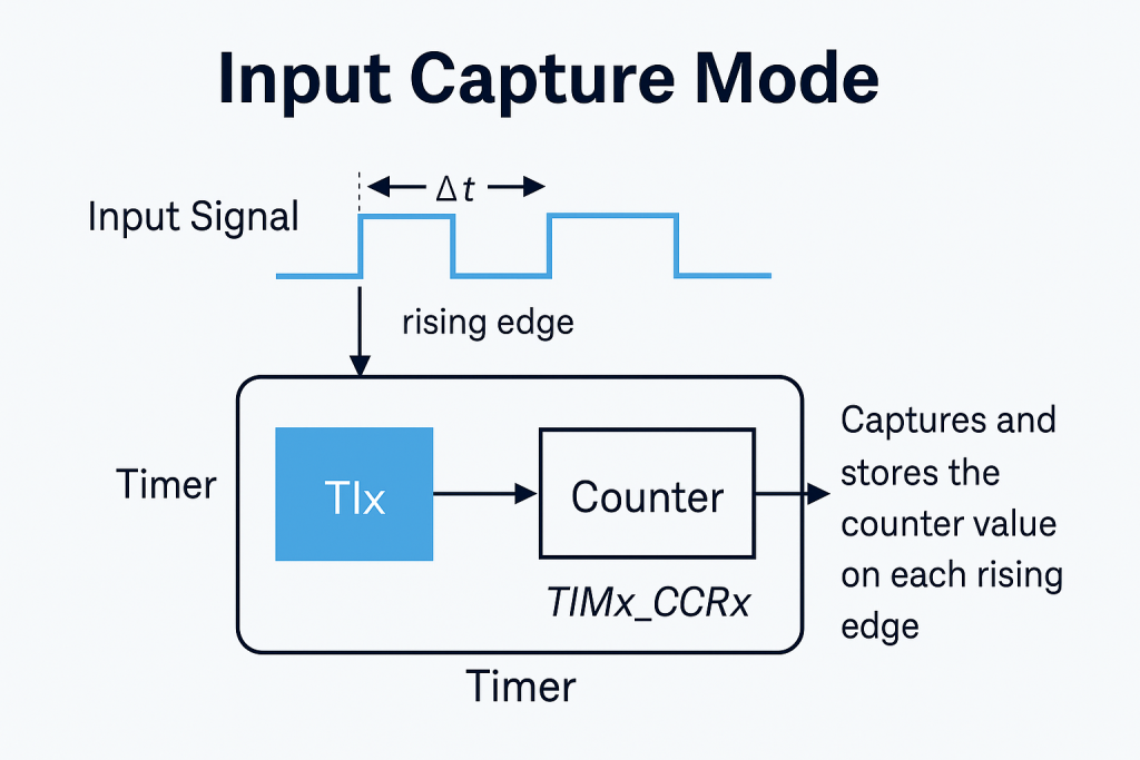
Input Capture is a feature of STM32 timers that allows the microcontroller to record the exact timer count value when an external event (signal edge) occurs on a designated input pin. It works by latching the current value of a running timer into a capture register when a rising, falling, or both edges are detected on a specific channel (e.g., TIMx_CH1).
Instead of manually checking the signal in software, Input Capture automatically and accurately timestamps external events, with zero CPU delay, using hardware support.
How It Works
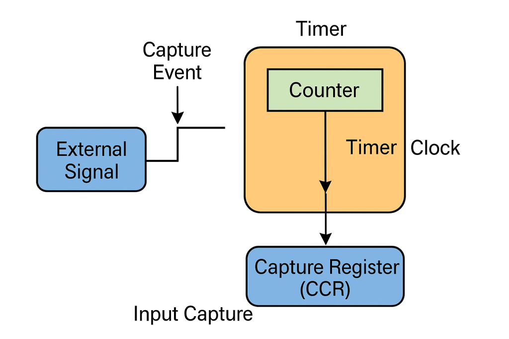
- A timer (e.g., TIM2) is running with a known clock frequency.
- An external signal is connected to a timer input capture channel pin (e.g., PA0 for TIM2_CH1).
- On detecting a configured edge (rising/falling), the timer’s current count value is stored in a capture register(CCR1).
- Software can read the captured value to calculate time difference between events.
Applications of Input Capture
- Measuring Signal Period or Frequency
Capture timestamps on consecutive rising edges to calculate the period, then derive the frequency. - Pulse Width Measurement
- Capture on rising edge (start of pulse).
- Capture on falling edge (end of pulse).
- Subtract the two to get pulse width.
- Event Timestamping
Useful in data logging, industrial automation, or protocols needing precise event timing. - Speed Measurement (Tachometer)
Capture intervals between pulses from a wheel encoder or fan tach signal to calculate speed. - Ultrasonic Distance Measurement
- Send pulse.
- Use Input Capture to measure echo return time.
- IR Remote Decoding
Capture pulse widths in IR signals for decoding remote control commands. - Communication Protocol Timing
Useful in protocols like LIN or custom asynchronous protocols to capture start/stop bits or sync pulses.
Advantages
- High accuracy (hardware-timed)
- Low CPU overhead
- Suitable for high-speed or irregular signals
2. STM32CubeIDE Setup:
pen STM32CubeIDE after selecting the workspace and create new project as following:

Select the MCU:

Give the project a name:
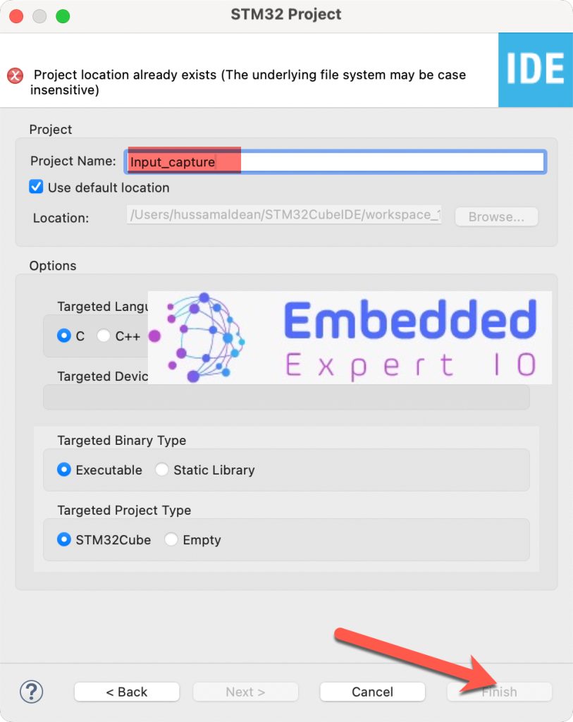
Click on finish.
Next, STM32CubeMX Window will appear.
From the window, select Clock Configuration as following:
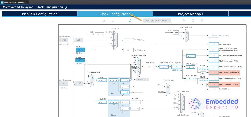
Notice timers clock. Since STM32F4 has default frequency of 16MHz, hence timers frequency is 16MHz.
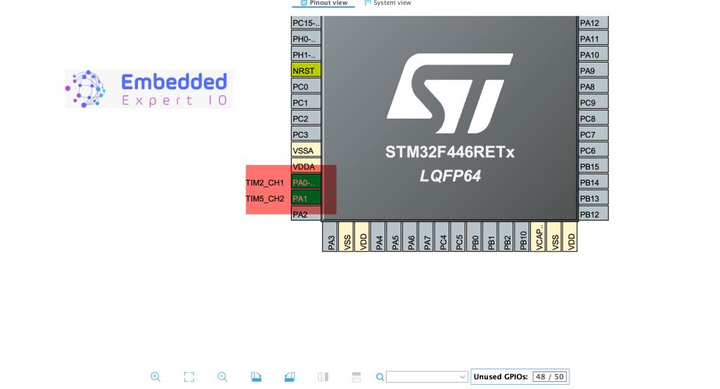
Next, set PA0 and PA1 as TIM2_CH1 and TIM5_CH2 respectively as follows:
After the pins have been set to the required functions. Next, we shall setup timer 2 as input capture.
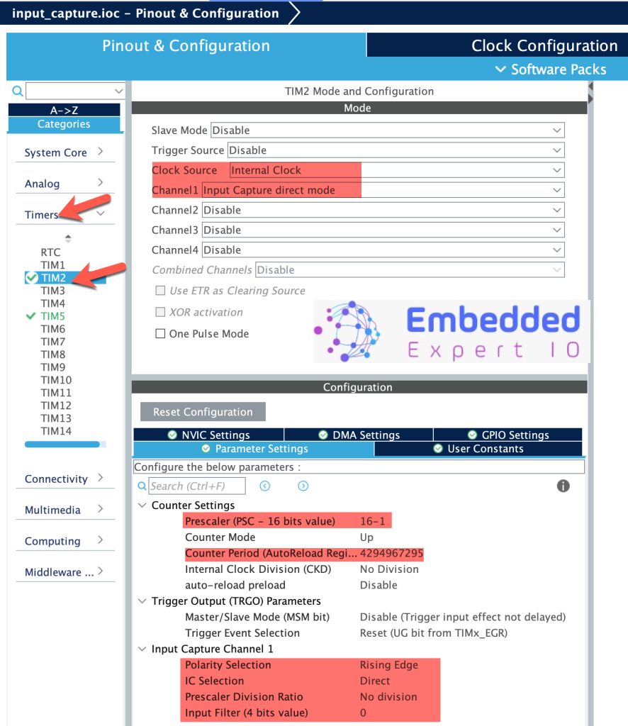
From Timers, select TIM2 and configure it as follows:
- Clock Source to Internal Clock.
- Channel1 as Input Capture direct mode.
From the Parameters, set the following:
- Set the prescaler to 16MHz which will make the timer operates at 1MHz.
- Keep the counter period to maximum and the rest as the default.
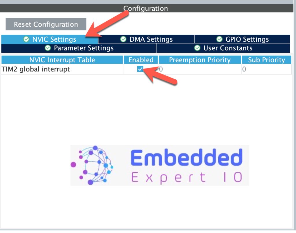
Next, from NVIC settings, enable NVIC for TIM2 as follows:
Next, we shall configure TIM5 as output compare, for more information about output compare mode, please refer to this guide.
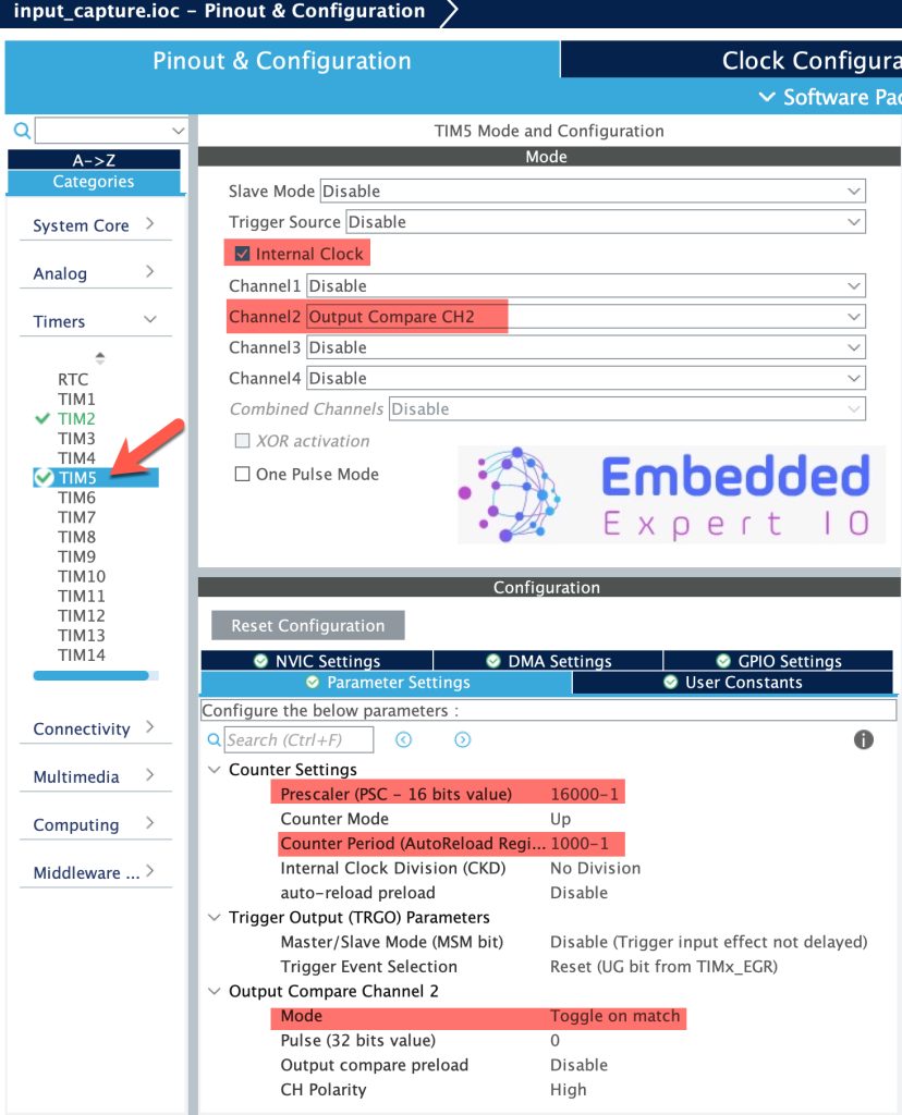
Configure the TIM5 as follows:
- Clock source to internal clock.
- Channel2 as Output Compare CH2.
- Prescaler to 16000-1.
- Perioid to 1000-1.
- Mode to toggle on match.
In this configuration, TIM5 shall provide toggle rate of 1Hz (1 second high and 1 second low).
Thats all for the guide, save the project and this will generate the project.
3. Connection:
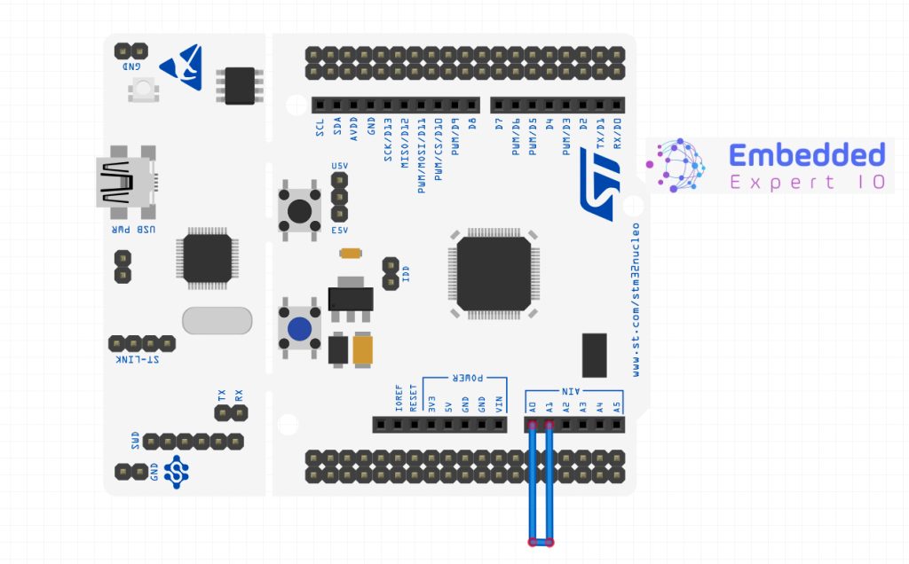
The connection as simple as connecting jumper wires between PA0 and PA1. In case of Nucleo-64 board, connect A0 arduino pin to A1 Arduino pin as shown below:
4. Firmware Development:
Once the code has been generated, main.c file shall open.
In main.c, in user code begin PV declare the following variables:
volatile uint32_t IC_Value1 = 0;
volatile uint32_t IC_Value2 = 0;
volatile uint32_t Period_Ticks = 0;
volatile uint8_t is_first_captured = 0;
IC_Valuex is store the period between each rising edges.
Period to calculate the total time between each edge.
is_first_captured is used to control the follow.
In user code begin0, declare the following:
void HAL_TIM_IC_CaptureCallback(TIM_HandleTypeDef *htim)
{
    if (htim->Instance == TIM2 && htim->Channel == HAL_TIM_ACTIVE_CHANNEL_1)
    {
        if (is_first_captured == 0)
        {
            IC_Value1 = HAL_TIM_ReadCapturedValue(htim, TIM_CHANNEL_1);
            is_first_captured = 1;
        }
        else
        {
            IC_Value2 = HAL_TIM_ReadCapturedValue(htim, TIM_CHANNEL_1);

            if (IC_Value2 > IC_Value1)
                Period_Ticks = IC_Value2 - IC_Value1;
            else
              	/*Overflow control*/
                Period_Ticks = (0xFFFFFFFF - IC_Value1 + 1) + IC_Value2;

            is_first_captured = 0;  // Ready for next measurement
        }
    }
}
The function shall be called each timer a rising edge is detected on TIM2_Channel1 pin.
The function first checks if the interrupt source is timer2 and channel1 is the source.
If it is, check if it is first capture, if it is not, store the captured value into IC_Value1 and set is_first_capture to 1.
Once the next edge is detected, store the captured value into IC_Value2.
Then calculate the period by subtracting Value2 from Value1. Also, there is overflow management in case if the timer overflows and reset is_first_captured.
In user code begin 3 in main function:
Start TIM2 in Input capture mode with interrupt and TIM5 in output compare as follows:
  HAL_TIM_IC_Start_IT(&htim2, TIM_CHANNEL_1);
  HAL_TIM_OC_Start(&htim5, TIM_CHANNEL_2);
Thats all for the guide.
Build the project and start a debugging session as following:

5. Results:
In live expression add period to monitor the value:
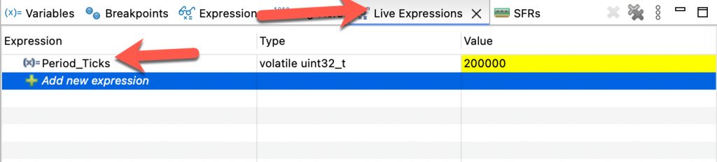
From TIM5, the time between each rising edge is 2 seconds. The measured period by TIM2 is 2 Millions ticks. Since the timer frequency is 1MHz, that means 2 millions ticks/1 millions ticks/second, you will get 2 seconds which is the same as we set TIM5 to generate.
Happy coding 😉
Add Comment