
In this article, we will took at the RFID and how it does work and use RC522 to read RFID tag and display the tag ID on I2C LCD.
In this article, we will cover the following:
- What is RFID.
- RC522 RFID module.
- Connection with STM32.
- Code.
- Demo.
1. What is RFID:
RFID (radio frequency identification) is a form of wireless communication that incorporates the use of electromagnetic or electrostatic coupling in the radio frequency portion of the electromagnetic spectrum to uniquely identify an object, animal or person.
How does RFID work?
Every RFID system consists of three components: a scanning antenna, a transceiver and a transponder. When the scanning antenna and transceiver are combined, they are referred to as an RFID reader or interrogator. There are two types of RFID readers — fixed readers and mobile readers. The RFID reader is a network-connected device that can be portable or permanently attached. It uses radio waves to transmit signals that activate the tag. Once activated, the tag sends a wave back to the antenna, where it is translated into data.
The transponder is in the RFID tag itself. The read range for RFID tags varies based on factors including the type of tag, type of reader, RFID frequency and interference in the surrounding environment or from other RFID tags and readers. Tags that have a stronger power source also have a longer read range.
For more information, please check this youtube video (here).
2.1 RC522 RFID module:
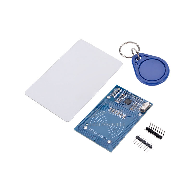
The RC522 RFID module based on MFRC522 IC from NXP is one of the most inexpensive RFID options that you can get online for less than four dollars. It usually comes with a RFID card tag and key fob tag having 1KB memory. And best of all, it can write a tag, so you can store your some sort of secret message in it.
he RC522 RFID Reader module is designed to create a 13.56MHz electromagnetic field that it uses to communicate with the RFID tags (ISO 14443A standard tags). The reader can communicate with a microcontroller over a 4-pin Serial Peripheral Interface (SPI) with a maximum data rate of 10Mbps. It also supports communication over I2C and UART protocols.
The module comes with an interrupt pin. It is handy because instead of constantly asking the RFID module “is there a card in view yet? “, the module will alert us when a tag comes into its vicinity.
The operating voltage of the module is from 2.5 to 3.3V, but the good news is that the logic pins are 5-volt tolerant, so we can easily connect it to any 5V logic microcontroller without using any logic level converter.
Here are complete specifications:
| Frequency Range | 13.56 MHz ISM Band |
| Host Interface | SPI / I2C / UART |
| Operating Supply Voltage | 2.5 V to 3.3 V |
| Max. Operating Current | 13-26mA |
| Min. Current(Power down) | 10µA |
| Logic Inputs | 5V Tolerant |
| Read Range | 5 cm |
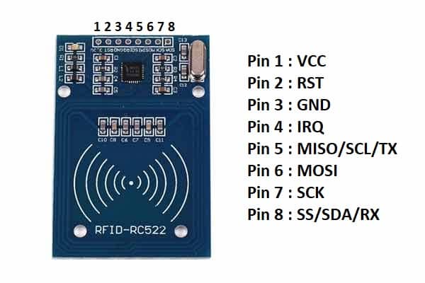
2.2 RC522 pinout:
The RC522 module has total 8 pins that interface it to the outside world. The connections are as follows:
| Pin | Description |
| VCC | supplies power for the module. This can be anywhere from 2.5 to 3.3 volts. You can connect it to 3.3V output. Remember connecting it to 5V pin will likely destroy your module! |
| RST | an input for Reset and power-down. When this pin goes low, hard power-down is enabled. This turns off all internal current sinks including the oscillator and the input pins are disconnected from the outside world. On the rising edge, the module is reset. |
| GND | the Ground Pin and needs to be connected to GND pin on the Arduino. |
| IRQ | pin acts as Master-In-Slave-Out when SPI interface is enabled, acts as serial clock when I2C interface is enabled and acts as serial data output when UART interface is enabled. |
| MISO | is SPI input to the RC522 module. |
| MOSI | is SPI input to the RC522 module. |
| SCK | accepts clock pulses provided by the SPI bus Master. |
| SS | pin acts as Signal input when SPI interface is enabled, acts as serial data when I2C interface is enabled and acts as serial data input when UART interface is enabled. This pin is usually marked by encasing the pin in a square so it can be used as a reference for identifying the other pins. |
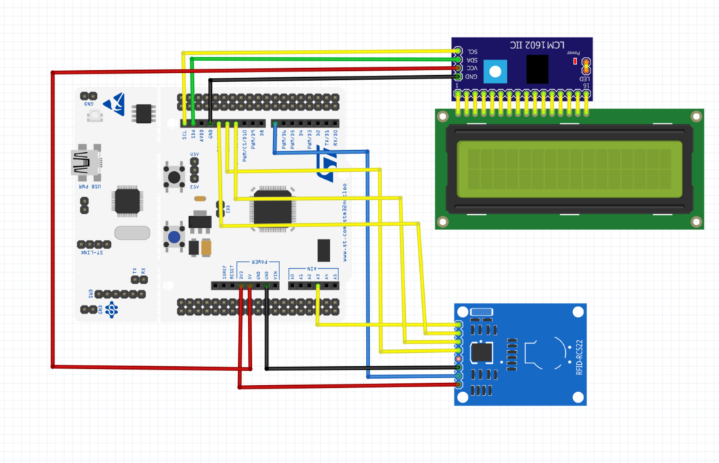
3. Connection with STM32F446 Nucleo:
| RC522 | STM32F446 Nucleo |
| Vcc | 3V3 |
| RST | PA8 (D7) |
| GND | GND |
| MOSI | PA7 (D11) |
| MISO | PA6 (D12) |
| SCK | PA5 (D13) |
| CS | PB0 (A3) |
| IRQ | Not connected |
4. Code:
We start off by configuring SPI as following:
void SPI_Init(void)
{
	#define AF5 0x05
	RCC->AHB1ENR|=RCC_AHB1ENR_GPIOAEN; //enable clock forn gpio a
	RCC->APB2ENR|=RCC_APB2ENR_SPI1EN; //enable clock for spi1
	GPIOA->MODER|=GPIO_MODER_MODE5_1|GPIO_MODER_MODE6_1|GPIO_MODER_MODE7_1;
	GPIOA->MODER&=~(GPIO_MODER_MODE5_0|GPIO_MODER_MODE6_0|GPIO_MODER_MODE7_0);
	GPIOA->OSPEEDR|=GPIO_OSPEEDER_OSPEEDR5|GPIO_OSPEEDER_OSPEEDR6|GPIO_OSPEEDER_OSPEEDR7;

	GPIOA->AFR[0]|=(AF5<<20)|(AF5<<24)|(AF5<<28);
	SPI1->CR2=0;
	SPI1->CR1=SPI_CR1_SSM|SPI_CR1_MSTR|SPI_CR1_BR_2|SPI_CR1_SSI|SPI_CR1_SPE;
}
Then SPI transmit as following:
int8_t SPI_Transmit(uint8_t *data, uint32_t size)
{


	uint32_t i		=0;
	uint8_t  temp	=0;
	uint32_t start=millis();
	temp =SPI1->DR;
	temp=SPI1->SR;
	while(i<size)
		{
		while(!((SPI1->SR)&SPI_SR_TXE)){if(millis()-start>1000){
			printf("TXE timed out\r\n");
			return -1;}} // wait to transmision buffer to be emplty
		SPI1->DR= data[i];
		while(!(SPI1->SR&SPI_SR_BSY)){if(millis()-start>1000){printf("BSY timed out\r\n");return -1;}}
		i++;
		}
while(!((SPI1->SR)&SPI_SR_TXE)){if(millis()-start>1000){printf("TXE2 time dout\r\n");return -1;}}
while((SPI1->SR)&SPI_SR_BSY){if(millis()-start>1000){printf("BSY2 timed out\r\n"); return -1;}}
temp =SPI1->DR;
temp=SPI1->SR;
return 0;
}
SPI receive function:
int8_t SPI_Receive(uint8_t *data, uint32_t size)
{
while(size)
		{
	uint32_t start=millis();
		SPI1->DR=0;
		while(!(SPI1->SR&SPI_SR_RXNE)){if(millis()-start>200){return -1;}}
		*data++=(SPI1->DR);
			size--;
		}
return 0;
}
Now for the RC522 initializing function as following:
void rc522_init(void)
{
	/*
	 * STM32 ->RFID
	 * SPI  -> SPI
	 * PA8  ->RST
	 * PB0  ->CS
	 * */
  SPI_Init();
  GPIOA->MODER|=GPIO_MODER_MODE8_0;
  GPIOA->MODER&=~GPIO_MODER_MODE8_1;

  RCC->AHB1ENR|=RCC_AHB1ENR_GPIOBEN;

  GPIOB->MODER|=GPIO_MODER_MODE0_0;
  GPIOB->MODER&=~GPIO_MODER_MODE0_1;
  GPIOA->BSRR=GPIO_BSRR_BR8;
  for(volatile int i=0;i<100000;i++);
  GPIOA->BSRR=GPIO_BSRR_BS8;
  for(volatile int i=0;i<100000;i++);
  rc522_reset();

  rc522_regWrite8(MFRC522_REG_T_MODE, 0x80);
  rc522_regWrite8(MFRC522_REG_T_PRESCALER, 0xA9);
  rc522_regWrite8(MFRC522_REG_T_RELOAD_L, 0xE8);
  rc522_regWrite8(MFRC522_REG_T_RELOAD_H, 0x03);


  rc522_regWrite8(MFRC522_REG_TX_AUTO, 0x40);
  rc522_regWrite8(MFRC522_REG_MODE, 0x3D);

  rc522_antennaON();   //Open the antenna
}
Register read and write:
uint8_t rc522_regRead8(uint8_t reg)
{
spi_cs_rfid_write(0);
reg = ((reg << 1) & 0x7E) | 0x80;
SPI_Transmit(®, 1);
uint8_t dataRd=0;
SPI_Receive(&dataRd, 1);
spi_cs_rfid_write(1);
return dataRd;
}
/**
* @brief write register
*/
void rc522_regWrite8(uint8_t reg, uint8_t data8)
{
spi_cs_rfid_write(0);
uint8_t txData[2] = {0x7E&(reg << 1), data8};
SPI_Transmit(txData, 2);
spi_cs_rfid_write(1);
}other functions required:
bool rc522_toCard(
    uint8_t command,
    uint8_t* sendData,
    uint8_t sendLen,
    uint8_t* backData,
    uint16_t* backLen);

bool rc522_request(uint8_t reqMode, uint8_t *tagType);

bool rc522_antiColl(uint8_t* serNum);

void spi_cs_rfid_write(bool state)
{
	if(state)
	  {
	    GPIOB->ODR |= (1UL << 0);
	  }
	  else
	  {
	    GPIOB->ODR &= ~(1UL << 0);
	  }
}

/**
 * @brief set bit
 */
void rc522_setBit(uint8_t reg, uint8_t mask)
{
  rc522_regWrite8(reg, rc522_regRead8(reg)|mask);
}

/**
 * @brief clear bit
 */
void rc522_clearBit(uint8_t reg, uint8_t mask)
{
  rc522_regWrite8(reg, rc522_regRead8(reg)&(~mask));
}

/**
 * @brief reset function
 */
void rc522_reset(void)
{
  rc522_regWrite8(0x01, 0x0F);
}

/**
 * @brief Antenna ON
 */
void rc522_antennaON(void)
{
  uint8_t temp;

  temp = rc522_regRead8(MFRC522_REG_TX_CONTROL);
  if (!(temp & 0x03)) {
    rc522_setBit(MFRC522_REG_TX_CONTROL, 0x03);
  }
}

/**
 * @brief Check card
 */
bool rc522_checkCard(uint8_t *id)
{
  bool status=false;
  //Find cards, return card type
    status = rc522_request(PICC_REQIDL, id);
    if (status == true) {
      //Card detected
      //Anti-collision, return card serial number 4 bytes
      status = rc522_antiColl(id);
    }
    rc522_halt();      //Command card into hibernation

    return status;
}

/**
 * @brief Request function
 */
bool rc522_request(uint8_t reqMode, uint8_t *tagType)
{
  bool status=false;
  uint16_t backBits;
  rc522_regWrite8(MFRC522_REG_BIT_FRAMING, 0x07);
  tagType[0] = reqMode;
  status = rc522_toCard(PCD_TRANSCEIVE, tagType, 1, tagType, &backBits);
  if ((status != true) || (backBits != 0x10)) {
    status = false;
  }
  return status;
}

/**
 * @brief to Card
 */
bool rc522_toCard(
    uint8_t command,
    uint8_t* sendData,
    uint8_t sendLen,
    uint8_t* backData,
    uint16_t* backLen)
{
  bool status = false;
  uint8_t irqEn = 0x00;
  uint8_t waitIRq = 0x00;
  uint8_t lastBits;
  uint8_t n;
  uint16_t i;

  switch (command) {
    case PCD_AUTHENT: {
      irqEn = 0x12;
      waitIRq = 0x10;
      break;
    }
    case PCD_TRANSCEIVE: {
      irqEn = 0x77;
      waitIRq = 0x30;
      break;
    }
    default:
      break;
  }

  rc522_regWrite8(MFRC522_REG_COMM_IE_N, irqEn | 0x80);
  rc522_clearBit(MFRC522_REG_COMM_IRQ, 0x80);
  rc522_setBit(MFRC522_REG_FIFO_LEVEL, 0x80);

  rc522_regWrite8(MFRC522_REG_COMMAND, PCD_IDLE);

  //Writing data to the FIFO
  for (i = 0; i < sendLen; i++) {
    rc522_regWrite8(MFRC522_REG_FIFO_DATA, sendData[i]);
  }

  //Execute the command
  rc522_regWrite8(MFRC522_REG_COMMAND, command);
  if (command == PCD_TRANSCEIVE) {
    rc522_setBit(MFRC522_REG_BIT_FRAMING, 0x80);   //StartSend=1,transmission of data starts
  }

  //Waiting to receive data to complete
  i = 100;  //i according to the clock frequency adjustment, the operator M1 card maximum waiting time 25ms???
  do {
    //CommIrqReg[7..0]
    //Set1 TxIRq RxIRq IdleIRq HiAlerIRq LoAlertIRq ErrIRq TimerIRq
    n = rc522_regRead8(MFRC522_REG_COMM_IRQ);
    i--;
  } while ((i!=0) && !(n&0x01) && !(n&waitIRq));

  rc522_clearBit(MFRC522_REG_BIT_FRAMING, 0x80);     //StartSend=0

  if (i != 0)  {
    if (!(rc522_regRead8(MFRC522_REG_ERROR) & 0x1B)) {
      status = true;
      if (n & irqEn & 0x01) {
        status = false;
      }

      if (command == PCD_TRANSCEIVE) {
        n = rc522_regRead8(MFRC522_REG_FIFO_LEVEL);
        uint8_t l = n;
        lastBits = rc522_regRead8(MFRC522_REG_CONTROL) & 0x07;
        if (lastBits) {
          *backLen = (n - 1) * 8 + lastBits;
        } else {
          *backLen = n * 8;
        }

        if (n == 0) {
          n = 1;
        }
        if (n > MFRC522_MAX_LEN) {
          n = MFRC522_MAX_LEN;
        }

        //Reading the received data in FIFO
        for (i = 0; i < n; i++) {
          uint8_t d = rc522_regRead8(MFRC522_REG_FIFO_DATA);
          if (l == 4)
            printf("%02x ", d);
          backData[i] = d;
        }
        if (l==4)
          printf("\r\n");
        return status;
      }
    } else {
      printf("error\r\n");
      status = false;
    }
  }

  return status;
}

bool rc522_antiColl(uint8_t* serNum)
{
  bool status;
  uint8_t i;
  uint8_t serNumCheck = 0;
  uint16_t unLen;
  //for (i = 0; i < 4; i++)
//    printf("Anticoll In %d: 0x%02x\r\n", i, serNum[i]);


  rc522_regWrite8(MFRC522_REG_BIT_FRAMING, 0x00);    //TxLastBists = BitFramingReg[2..0]

  serNum[0] = PICC_ANTICOLL;
  serNum[1] = 0x20;
  status = rc522_toCard(PCD_TRANSCEIVE, serNum, 2, serNum, &unLen);

  //for (i = 0; i < 4; i++)
//      printf("Anticoll ToCard %d: 0x%02x\r\n", i, serNum[i]);

  if (status == true) {
    //Check card serial number
    for (i = 0; i < 4; i++) {
      serNumCheck ^= serNum[i];
    }
    if (serNumCheck != serNum[i]) {
      status = false;
    }
  }
  return status;
}

void rc522_halt(void)
{
  uint16_t unLen;
  uint8_t buff[4];

  buff[0] = PICC_HALT;
  buff[1] = 0;
  rc522_calculateCRC(buff, 2, &buff[2]);

  rc522_toCard(PCD_TRANSCEIVE, buff, 4, buff, &unLen);
}

void rc522_calculateCRC(uint8_t*  pIndata, uint8_t len, uint8_t* pOutData)
{
  uint8_t i, n;

  rc522_clearBit(MFRC522_REG_DIV_IRQ, 0x04);     //CRCIrq = 0
  rc522_setBit(MFRC522_REG_FIFO_LEVEL, 0x80);      //Clear the FIFO pointer
  //Write_MFRC522(CommandReg, PCD_IDLE);

  //Writing data to the FIFO
  for (i = 0; i < len; i++) {
    rc522_regWrite8(MFRC522_REG_FIFO_DATA, *(pIndata+i));
  }
  rc522_regWrite8(MFRC522_REG_COMMAND, PCD_CALCCRC);

  //Wait CRC calculation is complete
  i = 0xFF;
  do {
    n = rc522_regRead8(MFRC522_REG_DIV_IRQ);
    i--;
  } while ((i!=0) && !(n&0x04));      //CRCIrq = 1

  //Read CRC calculation result
  pOutData[0] = rc522_regRead8(MFRC522_REG_CRC_RESULT_L);
  pOutData[1] = rc522_regRead8(MFRC522_REG_CRC_RESULT_M);
}

/**
 * @brief compare IDs
 */
bool rc522_compareIds(uint8_t *idCurrent, uint8_t *idReference)
{
  uint8_t i;
  for(i=0; i<4;i++)
  {
    if(idCurrent[i] != idReference[i])
    {
      return false;
    }
  }
  return true;
}
In main.c file, we start by including the following:
#include "LiquidCrystal_PCF8574.h"
#include "delay.h"
#include "stdio.h"
#include "rfid.h"
delay is based on systick (from here) and the lcd is i2c based one (here).
variable to hold RFID code
uint8_t rfid_id[4];
hence main function and while loop as following:
int main(void)
		{
		//SysClockConfig();
		systick_init_ms(16000000);
		rc522_init();
		lcd_init();
		setCursor(0,0);
		lcd_send_string("RFID RC522 with");
		setCursor(7,1);
		lcd_send_string("STM32F4");
		setCursor(0,2);
		lcd_send_string("EmbeddedExperIO");
		delay(2000);
		lcd_clear();
		while(1)
				{
				if(rc522_checkCard(rfid_id))
							{

							lcd_clear();
							char data[20];
							setCursor(0,0);
							lcd_send_string("RFID code is");
							setCursor(0,1);
							sprintf(data,"0x%x 0x%x 0x%x 0x%x",rfid_id[0],rfid_id[1],rfid_id[2],rfid_id[3]);
							lcd_send_string(data);
							delay(1000);
							}
				delay(100);
				}

		}
you may download the code from here
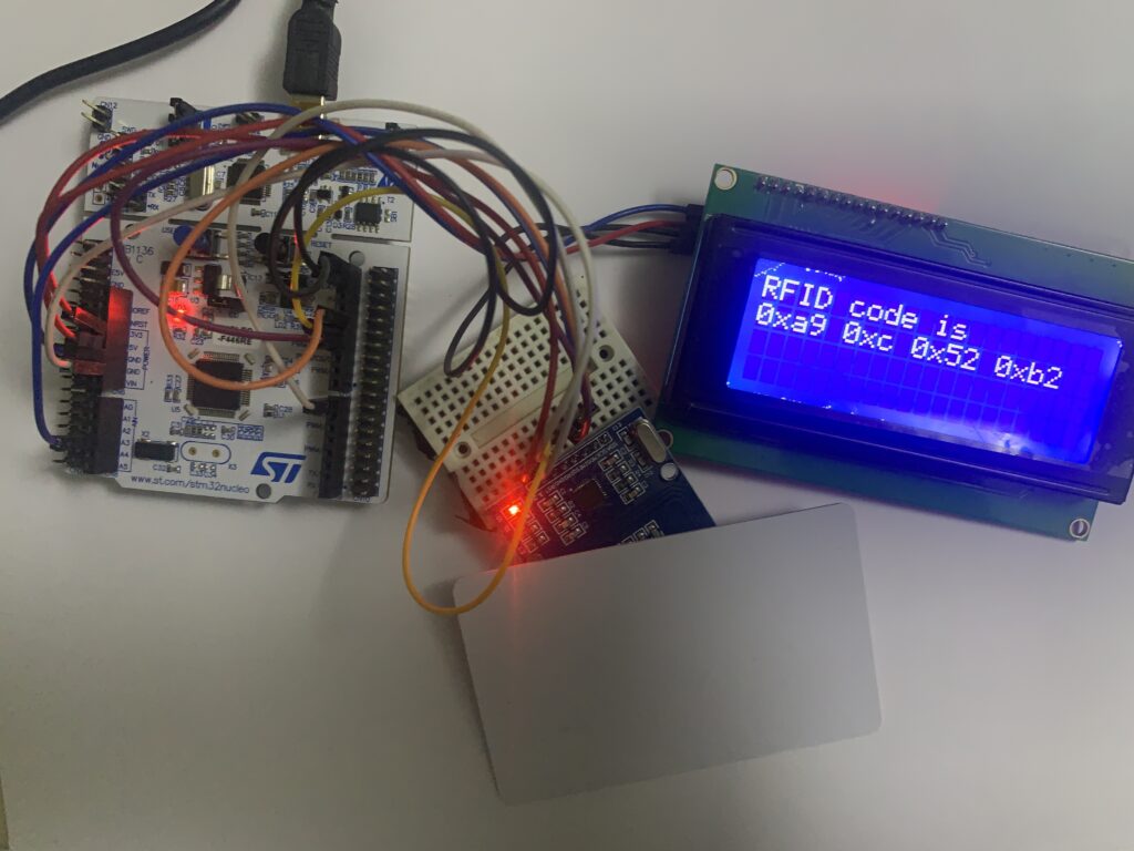
5. Results:
Once the code is compiled and uploaded to MCU, place a card on the module and the result shall appear as following:
Happy coding 🙂
30 Comments
Hello, first of all, thank you, it was really helpful, may ı ask which program did u use while drawing the scheme in part 3 (Connection with STM32F446 Nucleo – https://blog.embeddedexpert.io/wp-content/uploads/2022/02/Screen-Shot-2022-02-15-at-7.34.12-AM-1536×990.png)
Hi,
I used fritzing.
thank you, but ı couldn’t find STM32F446 Nucleo, how can find it and other components by searching
Just search for Nucleo-64 for fritzing using google.
which software have you used for simulation
Hi,
Fritzing
thanks
thankyou
any ways of getting frtizing for free?
If you need the software, pay for it.
As simple as that.
ok but after downloading the software do we need to import any libraries for stm32 nucleo board??
Just search google for Nucleo-64 Fritzing
Hello, how can ı get the “rfid.h” library, Did you create it by yourself, or just insert it from a website, etc?
You can download the entire source code.
after flashing the code on the board the message appears after pressing the button on the board but the card doesn’t get scanned. Any idea y this is happening
Hi,
download the source code and upload it using Keil uVision.
OR modify the code to make it work wit STM32CubeIDE.
Also, I am using here STM32F446RE.
yeah i am using the same board and i have used keil itself. do i need to do any other changes for the entire project to work. ignore the other comment which i have posted
Check the variable rfid_id and see if it is updating.
Note: remove anything related to LCD.
it’s not updating what do i do??
I tried the code and indeed doesn’t work.
I’ll port this to STM32CubeIDE later.
Meanwhile, test with ARM Compiler V5 since the newer version doesn’t have V5.
can u please tell me the packages to be downloaded on keil
I’ll check the code from my end and report back.
does the code even work?? which packages do i need to install??
You need to install STM32F4 package
Hi ! Can I use stm32f103c8t6 ?
Yes, you can.
Just modify the SPI driver.
Hey how can I modify this code to work with stm32l476RGT board ? Please help, I have tried changing some things for the SPI but I keep getting the version error and my antenna is getting disabled
Use HAL with STM32CubeIDE.
This will fix the SPI issues in L4.
Hi i am using a STM32F407-DISC1 and facing the same issue of SPI communication dropping. How can i use your code with CUBE IDE i am using HAL library.
Hi,
take a look at the revised version:
https://blog.embeddedexpert.io/?p=1610
Add Comment