In this guide, we shall see how to work with TM1637 4-digit 7-segment LED display and use STM32F411 to display the encoder values on the display.
In this guide, we will cover the following :
- TM1637 4-digit 7-segment LED display
- Connection with STM32
- Code
- Demo
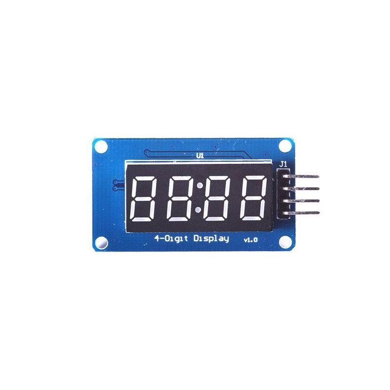
1. TM1637 4-digit 7-segment LED display:
Bare 4-digit 7-segment displays usually require 12 connection pins. That’s quite a lot and doesn’t leave much room for other sensors or modules. Thanks to the TM1637 IC mounted on the back of the display module, this number can be reduced to just four. Two pins are required for the power connections and the other two pins are used to control the segments.
7-segment displays contain 7 (or 8) individually addressable LEDs. The segments are labeled A to G and some displays also have a dot (the 8th LED). Use this image as a reference when setting the individual segments in the code later.

You can buy many different display modules that use a TM1637 IC. The color, size, dots, and connection points can all be different. I don’t have experience with all the different versions of this display but as long as they use the TM1637, the code examples provided below should work.
Here you can find the basic specifications of the display module that I used in this tutorial.
TM1637 4-Digit 7-Segment Display Specifications
| Operating voltage | 3.3 – 5 V |
| Current draw | 80 mA |
| Luminance levels | 8 |
| Display dimensions | 30 x 14 mm (0.36″ digits) |
| Overall dimensions | 42 x 24 x 12 mm |
| Hole dimensions | 38 x 20, ⌀ 2.2 mm |
| Operating temperature | -10 – 80 °C |
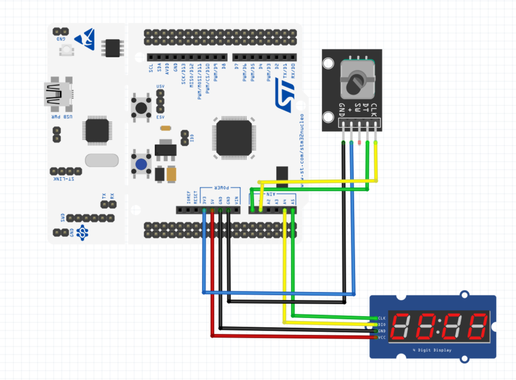
2. Connection with STM32
The connection of M1637 4-digit 7-segment LED display as following:
| TM1637 | STM32F411 Nucleo-64 |
| Vcc | 5V |
| GNG | GND |
| DIO | PC1 (A4) |
| CLK | PC0(A5) |
The encoder connection as following:
| Encoder Pin | STM32F411-Nucleo64 Pin |
| GND | GND |
| + | 3V3 |
| DT | PA0 |
| CLK | PA1 |
For encoder hookup guide and code, please refer to this topic
3. Code:
in tm1637.c file, we start of by defining some macros that will allow us access some functionality in the code later and segments definitions as following:
#define PORTC_CLK_ENABLE RCC->AHB1ENR|=RCC_AHB1ENR_GPIOCEN


#define CLK_PIN_ENABLE GPIOC->MODER|=(1<<0)|(0<<1)
#define DIO_PIN_ENABLE GPIOC->MODER|=(1<<2)|(0<<3)


const char segmentMap[] = {
    0x3f, 0x06, 0x5b, 0x4f, 0x66, 0x6d, 0x7d, 0x07, // 0-7
    0x7f, 0x6f, 0x77, 0x7c, 0x39, 0x5e, 0x79, 0x71, // 8-9, A-F
    0x00
};
For the initializing, we enable clock access to the port, set pins as output with internal pull-up and set brightness to 8
void tm1637Init(void)
{
	RCC->AHB1ENR|=RCC_AHB1ENR_GPIOCEN;
  GPIOC->MODER|=(1<<0)|(0<<1);
	GPIOC->MODER|=(1<<2)|(0<<3);
	GPIOC->OSPEEDR|=0xF;
	GPIOC->OTYPER|=(1<<0)|(1<<0);
	GPIOC->PUPDR|=(1<<0)|(1<<2);
	tm1637SetBrightness(8);
}
For displaying a decimal value, the following function is used:
void tm1637DisplayDecimal(int v, int displaySeparator)
{
    unsigned char digitArr[4];
    for (int i = 0; i < 4; ++i) {
        digitArr[i] = segmentMap[v % 10];
        if (i == 2 && displaySeparator) {
            digitArr[i] |= 1 << 7;
        }
        v /= 10;
    }

    _tm1637Start();
    _tm1637WriteByte(0x40);
    _tm1637ReadResult();
    _tm1637Stop();

    _tm1637Start();
    _tm1637WriteByte(0xc0);
    _tm1637ReadResult();

    for (int i = 0; i < 4; ++i) {
        _tm1637WriteByte(digitArr[3 - i]);
        _tm1637ReadResult();
    }

    _tm1637Stop();
}
To start the brightness, we can use the following function:
// Valid brightness values: 0 - 8.
// 0 = display off.
void tm1637SetBrightness(char brightness)
{
    // Brightness command:
    // 1000 0XXX = display off
    // 1000 1BBB = display on, brightness 0-7
    // X = don't care
    // B = brightness
    _tm1637Start();
    _tm1637WriteByte(0x87 + brightness);
    _tm1637ReadResult();
    _tm1637Stop();
}
For start, read results, write byte and stop, the functions shall be as following:
void _tm1637Start(void)
{
    _tm1637ClkHigh();
    _tm1637DioHigh();
    _tm1637DelayUsec(20);
    _tm1637DioLow();
}

void _tm1637Stop(void)
{
    _tm1637ClkLow();
    _tm1637DelayUsec(20);
    _tm1637DioLow();
    _tm1637DelayUsec(20);
    _tm1637ClkHigh();
    _tm1637DelayUsec(20);
    _tm1637DioHigh();
}

void _tm1637ReadResult(void)
{
    _tm1637ClkLow();
    _tm1637DelayUsec(50);
    // while (dio); // We're cheating here and not actually reading back the response.
    _tm1637ClkHigh();
    _tm1637DelayUsec(20);
    _tm1637ClkLow();
}

void _tm1637WriteByte(unsigned char b)
{
    for (int i = 0; i < 8; ++i) {
        _tm1637ClkLow();
        if (b & 0x01) {
            _tm1637DioHigh();
        }
        else {
            _tm1637DioLow();
        }
        _tm1637DelayUsec(30);
        b >>= 1;
        _tm1637ClkHigh();
        _tm1637DelayUsec(30);
    }
}
and finally delay as following:
void _tm1637DelayUsec(unsigned int i)
{
delayuS(i);
}
You may download the code from this github repository
Simple TM1637 Interface with STM32
4. Demo:
Happy coding 🙂
Add Comment