This guide demonstrates how to use an STM32 microcontroller to generate waveforms by updating the PWM duty cycle using a timer and DMA. By leveraging DMA, the duty cycle values are transferred efficiently without CPU intervention, enabling precise and continuous waveform output.
In this guide, we shall cover the following:
- Introduction and theory.
- STM32CubeIDE Setup.
- Firmware development.
- Results.
1. Introduction and Theory:
In embedded systems, generating analog-like waveforms using digital hardware is a widely-used technique in fields like motor control, lighting control (e.g., LED dimming), digital audio, and signal processing. One efficient and flexible method to generate such waveforms is by leveraging Pulse Width Modulation (PWM) combined with Direct Memory Access (DMA) on a microcontroller like the STM32F411RE.
What is PWM?
Pulse Width Modulation (PWM) is a method where a digital signal switches between HIGH and LOW states rapidly, with the proportion of time spent in the HIGH state—known as the duty cycle—defining the effective output level. For example, a 50% duty cycle means the signal is HIGH for half the period and LOW for the other half, which can be interpreted as an analog voltage level when filtered.
By changing the duty cycle over time in a controlled manner, PWM can simulate analog waveforms. If these duty cycle updates follow the shape of a sine, triangle, or custom pattern, the resulting output—after low-pass filtering—closely resembles the desired waveform.
Why Use DMA?
Changing the PWM duty cycle on every timer update through software can introduce timing jitter and CPU overhead. This becomes a bottleneck, especially at high PWM frequencies or fine waveform resolutions. Direct Memory Access (DMA) solves this problem by autonomously transferring data from memory (e.g., a waveform table) to the timer’s Compare Register (TIMx_CCRx) without CPU involvement.
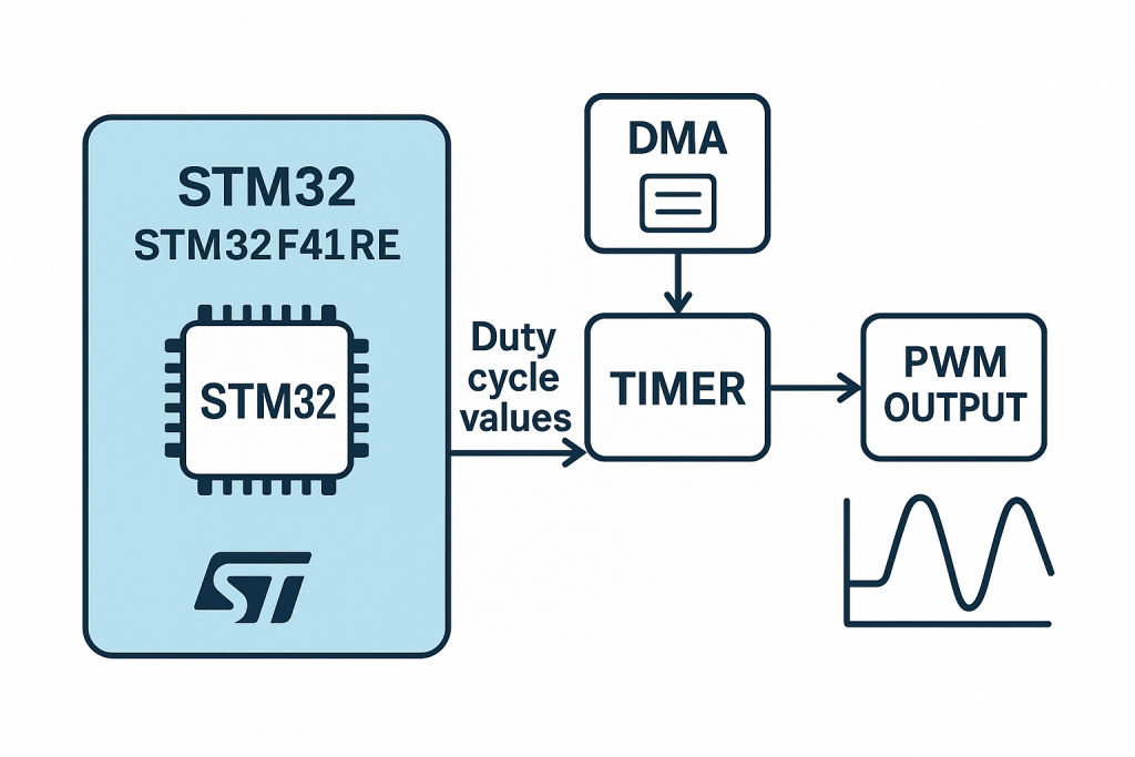
In this architecture:
- The Timer is configured in PWM mode with a fixed frequency.
- A lookup table holds the duty cycle values corresponding to the desired waveform.
- The DMA is set up in circular or normal mode to transfer these values to the timer’s CCR register.
- Once triggered (e.g., by timer update events), DMA continuously updates the duty cycle, enabling the hardware to produce a smooth waveform output.
This results in:
- Stable and precise timing for waveform generation.
- Very low CPU usage, ideal for real-time applications.
- Scalability, allowing higher resolution waveforms or additional control loops.
Application Overview
In this guide, we will implement this approach using the STM32F411RE Nucleo-64 development board. We will configure:
- TIMx as a PWM output timer.
- DMA stream/channel to transfer duty cycles to TIMx_CCRx.
- A waveform table, such as a discretized sine wave.
- GPIO pin to output the PWM signal.
- (Optional) A low-pass filter to smooth the output into a true analog waveform.
This method offers a highly efficient and hardware-accelerated solution for waveform generation, suitable for both beginners and advanced embedded developers.
2. STM32CubeIDE Setup:
Open STM32CubeIDE after selecting the workspace and create new project as following:

Select the MCU:

Give the project a name:
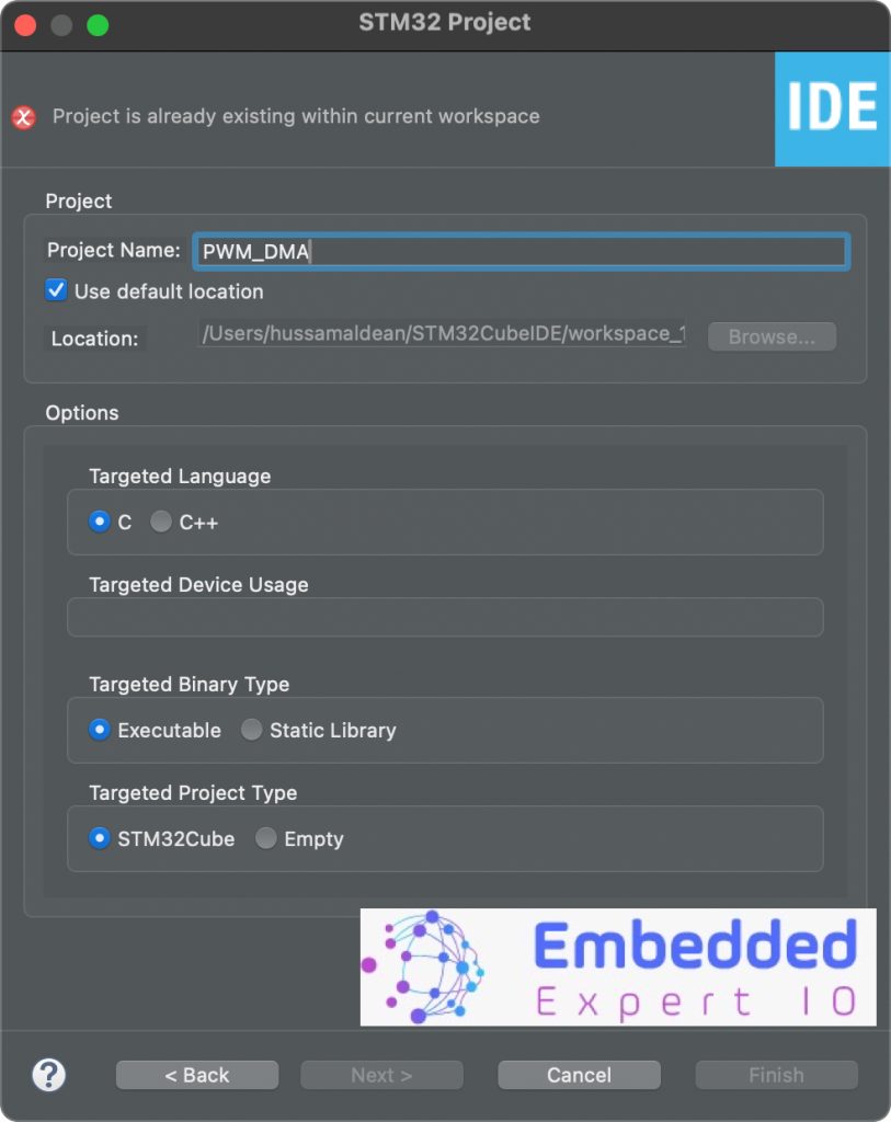
Click on finish.
Next, STM32CubeMX Window will appear.
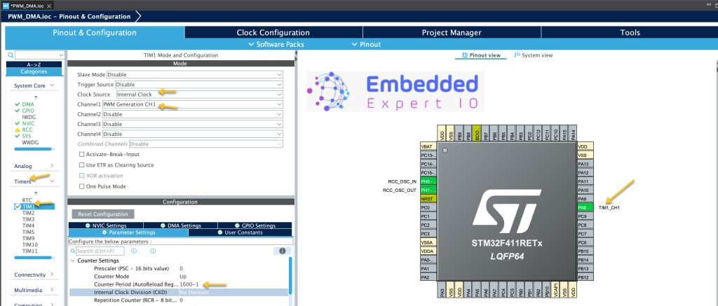
From timer, select TIM1:
Configure the timer as following:
- Clock Source to internal.
- Channel1 to be PWM Generation CH1. This will enable PA8.
- Set Counter Period to 1600-1.
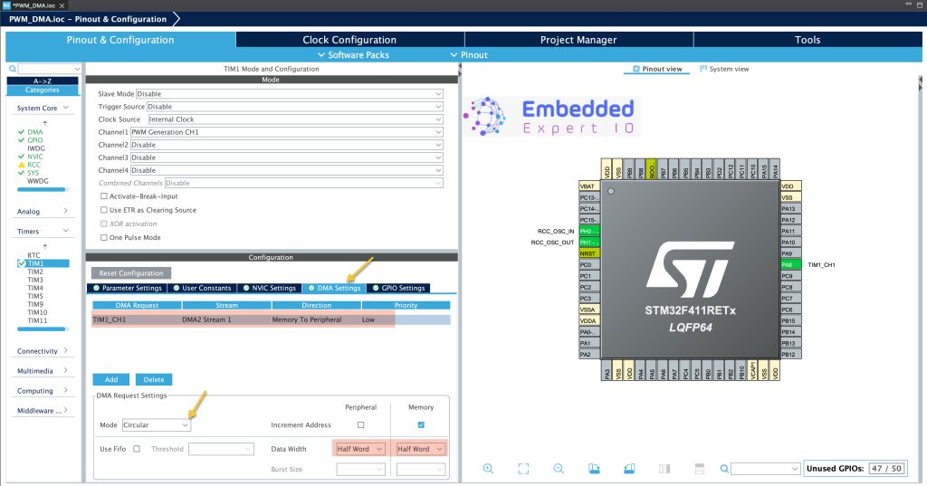
Next, in DMA configure the DMA as following:
- Request to be TIM1_CH1
- Mode to circular.
- Direction is Memory to Peripheral since are going to update the duty cycle.
- Priority according to your application.
Next, from NVIC in System Core, disable enforce DMA interrupt as following:
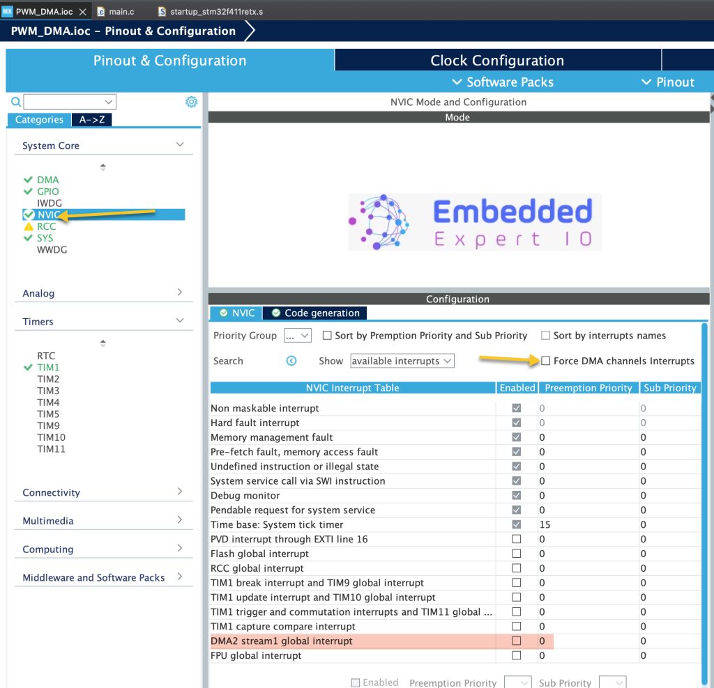
Feel free to keep the interrupt for the DMA. However, it is not needed in this guide, hence, it has been disabled.
Thats all for the configuration. Save the project and this will generate the project.
3. Firmware Development:
Once the project has been generated, main.c shall be opened.
In main.c in user begin PV, declare the following arrays:
// half sine wave PWM duty cycle (0 to 1599), 220 samples
uint16_t halfsine_duty[220] = {0,50 ,100 ,151 ,201 ,250 ,300 ,349 ,398 ,446 ,494 ,542 ,589 ,635 ,681
	,726 ,771 ,814 ,857 ,899 ,940 ,981 ,1020 ,1058 ,1095 ,1131 ,1166 ,1200 ,1233 ,1264
	,1294 ,1323 ,1351 ,1377 ,1402 ,1426 ,1448 ,1468 ,1488 ,1505 ,1522 ,1536 ,1550 ,1561
	,1572 ,1580 ,1587 ,1593 ,1597 ,1599 ,1600 ,1599 ,1597 ,1593 ,1587 ,1580 ,1572 ,1561
	,1550 ,1536 ,1522 ,1505 ,1488 ,1468 ,1448 ,1426 ,1402 ,1377 ,1351 ,1323 ,1294 ,1264
	,1233 ,1200 ,1166 ,1131 ,1095 ,1058 ,1020 ,981 ,940 ,899 ,857 ,814 ,771 ,726 ,681 ,635
	,589 ,542 ,494 ,446 ,398 ,349 ,300 ,250 ,201 ,151 ,100 ,50,0,50 ,100 ,151 ,201 ,250 ,300 ,349 ,398 ,446 ,494 ,542 ,589 ,635 ,681
			,726 ,771 ,814 ,857 ,899 ,940 ,981 ,1020 ,1058 ,1095 ,1131 ,1166 ,1200 ,1233 ,1264
			,1294 ,1323 ,1351 ,1377 ,1402 ,1426 ,1448 ,1468 ,1488 ,1505 ,1522 ,1536 ,1550 ,1561
			,1572 ,1580 ,1587 ,1593 ,1597 ,1599 ,1600 ,1599 ,1597 ,1593 ,1587 ,1580 ,1572 ,1561
			,1550 ,1536 ,1522 ,1505 ,1488 ,1468 ,1448 ,1426 ,1402 ,1377 ,1351 ,1323 ,1294 ,1264
			,1233 ,1200 ,1166 ,1131 ,1095 ,1058 ,1020 ,981 ,940 ,899 ,857 ,814 ,771 ,726 ,681 ,635
			,589 ,542 ,494 ,446 ,398 ,349 ,300 ,250 ,201 ,151 ,100 ,50
};

// Full sine wave PWM duty cycle (0 to 1599), 220 samples
uint16_t fullsine_duty[220] = {
    800, 822, 845, 867, 890, 912, 935, 957, 979, 1001, 1023, 1045, 1066, 1087, 1108, 1129, 1149, 1169, 1188, 1207,
    1226, 1244, 1262, 1279, 1296, 1312, 1328, 1343, 1358, 1372, 1386, 1399, 1411, 1423, 1434, 1445, 1455, 1465, 1474, 1482,
    1490, 1497, 1503, 1509, 1514, 1518, 1522, 1525, 1527, 1529, 1530, 1530, 1530, 1529, 1527, 1525, 1522, 1518, 1514, 1509,
    1503, 1497, 1490, 1482, 1474, 1465, 1455, 1445, 1434, 1423, 1411, 1399, 1386, 1372, 1358, 1343, 1328, 1312, 1296, 1279,
    1262, 1244, 1226, 1207, 1188, 1169, 1149, 1129, 1108, 1087, 1066, 1045, 1023, 1001, 979, 957, 935, 912, 890, 867,
    845, 822, 800, 777, 754, 732, 709, 687, 664, 642, 620, 598, 576, 554, 533, 512, 491, 471, 451, 431,
    412, 393, 375, 357, 340, 323, 307, 291, 276, 261, 247, 233, 220, 208, 196, 185, 174, 164, 154, 145,
    137, 129, 122, 116, 110, 105, 101, 97, 94, 92, 90, 90, 90, 90, 92, 94, 97, 101, 105, 110,
    116, 122, 129, 137, 145, 154, 164, 174, 185, 196, 208, 220, 233, 247, 261, 276, 291, 307, 323, 340,
    357, 375, 393, 412, 431, 451, 471, 491, 512, 533, 554, 576, 598, 620, 642, 664, 687, 709, 732, 754,
    777, 800
};


// Triangle wave PWM duty cycle (0 to 1599)
uint16_t triangle_duty[200] = {
    0, 16, 32, 48, 64, 80, 96, 112, 128, 144, 160, 176, 192, 208, 224, 240, 256, 272, 288, 304,
    320, 336, 352, 368, 384, 400, 416, 432, 448, 464, 480, 496, 512, 528, 544, 560, 576, 592, 608, 624,
    640, 656, 672, 688, 704, 720, 736, 752, 768, 784, 800, 816, 832, 848, 864, 880, 896, 912, 928, 944,
    960, 976, 992, 1008, 1024, 1040, 1056, 1072, 1088, 1104, 1120, 1136, 1152, 1168, 1184, 1200, 1216, 1232, 1248, 1264,
    1280, 1296, 1312, 1328, 1344, 1360, 1376, 1392, 1408, 1424, 1440, 1456, 1472, 1488, 1504, 1520, 1536, 1552, 1568, 1584,
    1599, 1583, 1567, 1551, 1535, 1519, 1503, 1487, 1471, 1455, 1439, 1423, 1407, 1391, 1375, 1359, 1343, 1327, 1311, 1295,
    1279, 1263, 1247, 1231, 1215, 1199, 1183, 1167, 1151, 1135, 1119, 1103, 1087, 1071, 1055, 1039, 1023, 1007, 991, 975,
    959, 943, 927, 911, 895, 879, 863, 847, 831, 815, 799, 783, 767, 751, 735, 719, 703, 687, 671, 655,
    639, 623, 607, 591, 575, 559, 543, 527, 511, 495, 479, 463, 447, 431, 415, 399, 383, 367, 351, 335,
    319, 303, 287, 271, 255, 239, 223, 207, 191, 175, 159, 143, 127, 111, 95, 79, 63, 47, 31, 15
};

// Sawtooth wave PWM duty cycle (0 to 1599)
uint16_t sawtooth_duty[200] = {
    0, 8, 16, 24, 32, 40, 48, 56, 64, 72, 80, 88, 96, 104, 112, 120, 128, 136, 144, 152,
    160, 168, 176, 184, 192, 200, 208, 216, 224, 232, 240, 248, 256, 264, 272, 280, 288, 296, 304, 312,
    320, 328, 336, 344, 352, 360, 368, 376, 384, 392, 400, 408, 416, 424, 432, 440, 448, 456, 464, 472,
    480, 488, 496, 504, 512, 520, 528, 536, 544, 552, 560, 568, 576, 584, 592, 600, 608, 616, 624, 632,
    640, 648, 656, 664, 672, 680, 688, 696, 704, 712, 720, 728, 736, 744, 752, 760, 768, 776, 784, 792,
    800, 808, 816, 824, 832, 840, 848, 856, 864, 872, 880, 888, 896, 904, 912, 920, 928, 936, 944, 952,
    960, 968, 976, 984, 992, 1000, 1008, 1016, 1024, 1032, 1040, 1048, 1056, 1064, 1072, 1080, 1088, 1096, 1104, 1112,
    1120, 1128, 1136, 1144, 1152, 1160, 1168, 1176, 1184, 1192, 1200, 1208, 1216, 1224, 1232, 1240, 1248, 1256, 1264, 1272,
    1280, 1288, 1296, 1304, 1312, 1320, 1328, 1336, 1344, 1352, 1360, 1368, 1376, 1384, 1392, 1400, 1408, 1416, 1424, 1432,
    1440, 1448, 1456, 1464, 1472, 1480, 1488, 1496, 1504, 1512, 1520, 1528, 1536, 1544, 1552, 1560, 1568, 1576, 1584, 1592
};
These arrays hold the duty cycles of each wave from. Each duty cycle represent the amplitude of the waveform.
In user code begin 2 in main function:
Start the PWM in DMA mode.
HAL_TIM_PWM_Start_DMA(&htim1, TIM_CHANNEL_1,(uint32_t)&sawtooth_duty,200);
The function HAL_TIM_PWM_Start_DMA Takes the following parameters:
- Instant to the timer, which is htim1 in this case.
- Timer channel, which is channel1 in this case.
- Array that holds the duty cycles (sawtooth) in this case.
- Size of the array which is 200 in this guide.
Thats all for the firmware and notice, we left the while 1 loop empty since everything has been handled by the DMA.
Save the project, build and run it on your board as following:

4. Results:
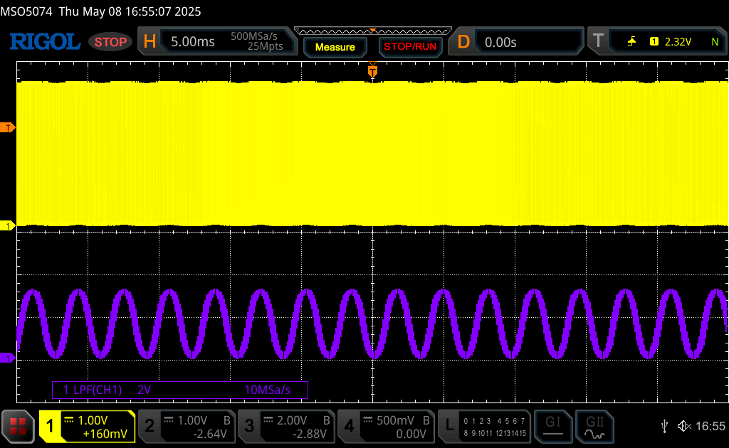
Using Low Pass Filter on the oscilloscope, you should get the following:
Sinewave:
Triangle:

Sawtooth:

We have successfully generated waveforms from PWM signal using DMA to update the duty cycle. This can be expanded even further to generate any type of waveform.
Happy coding 😉
Add Comment