Output Compare mode is a powerful feature of STM32 timers that allows generating precise events when the timer counter reaches a predefined value. It is commonly used for tasks like generating PWM signals, creating time-based triggers, or toggling output pins without CPU intervention.
In this guide, we will cover the following:
- Introduction and output compare application.
- STM32cubeIDE Setup.
- Firmware Development.
- Results.
1.1 Introduction:
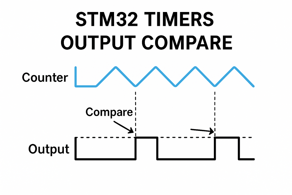
STM32 microcontrollers feature powerful and flexible timers that can be configured for a wide range of applications. One of the most commonly used features of these timers is the Output Compare (OC) mode. In Output Compare mode, the timer continuously counts up (or down) and compares its current value with a predefined value stored in a compare register (CCR – Capture/Compare Register). When the timer’s counter matches the compare value, a configurable output event occurs on a corresponding output pin, such as setting the pin high, clearing it low, toggling its state, or simply generating an internal event without affecting a pin.
The Output Compare functionality enables precise event timing without continuous CPU involvement, improving efficiency and reliability in embedded systems. This mechanism is particularly useful when deterministic timing behavior is required, such as generating waveforms, timing control signals, or triggering ADC conversions at precise intervals.
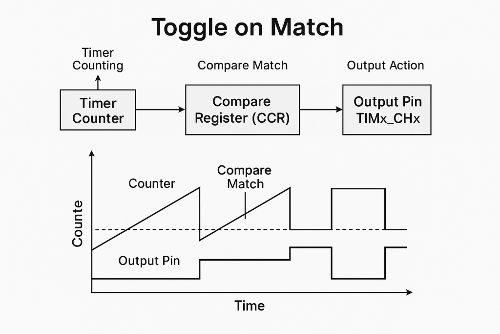
Among the different actions that can be taken upon a match, Toggle on Match is one of the most interesting. In this mode, every time the timer counter reaches the compare value, the output pin automatically toggles its state (from HIGH to LOW or LOW to HIGH). This simple behavior can be extremely powerful, allowing the generation of square waves or clock signals without using any CPU resources once configured. The toggle mode is especially beneficial for creating precise frequency signals — by adjusting the timer’s prescaler, auto-reload, and compare value, a wide range of output frequencies can be generated with minimal overhead.
For example, if the timer is set to count continuously and the Output Compare mode is set to “toggle on match,” the output will change its state every time the counter matches the compare value, effectively creating a signal with a frequency that depends on the timer’s clock settings and the compare value. This is very useful for applications such as generating clock signals for peripherals, simulating square waveforms, or blinking LEDs at a precise and stable rate.
1.2 Applications of Output Compare Mode
- Signal Generation (Square Waves and Clocks)
By configuring Output Compare to “Toggle on Match,” STM32 timers can generate clean and stable square waves for use as clocks for other devices, audio signals, or simple waveform generation. - Precise Event Scheduling
Output Compare can schedule specific events to happen at precise timer counts. For instance, you can trigger an ADC conversion, start a communication frame, or toggle an external device exactly when needed. - Pulse Generation
In automation and communication systems, short pulses may be needed at very precise intervals. Using Output Compare, the timer can generate a single pulse or a train of pulses with exact timing. - Motor Control
When combined with PWM (Pulse Width Modulation) applications, Output Compare can help to control motor speed or position by accurately generating switching signals. - Communication Protocols
Some protocols require strict timing for transmitting or receiving signals. Output Compare can automate timing-critical toggles, improving the reliability of such communications. - LED Blinking with Accurate Timing
Instead of using blocking delays or software counters, you can set up a timer channel in toggle mode to blink an LED at a precise rate without CPU load.
2. STM32CubeIDE Setup:
Open STM32CubeIDE after selecting the workspace and create new project as following:

Select the MCU:

Give the project a name:
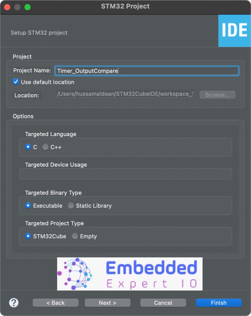
lick on finish.
Next, STM32CubeMX Window will appear.
From the window, select Clock Configuration as following:
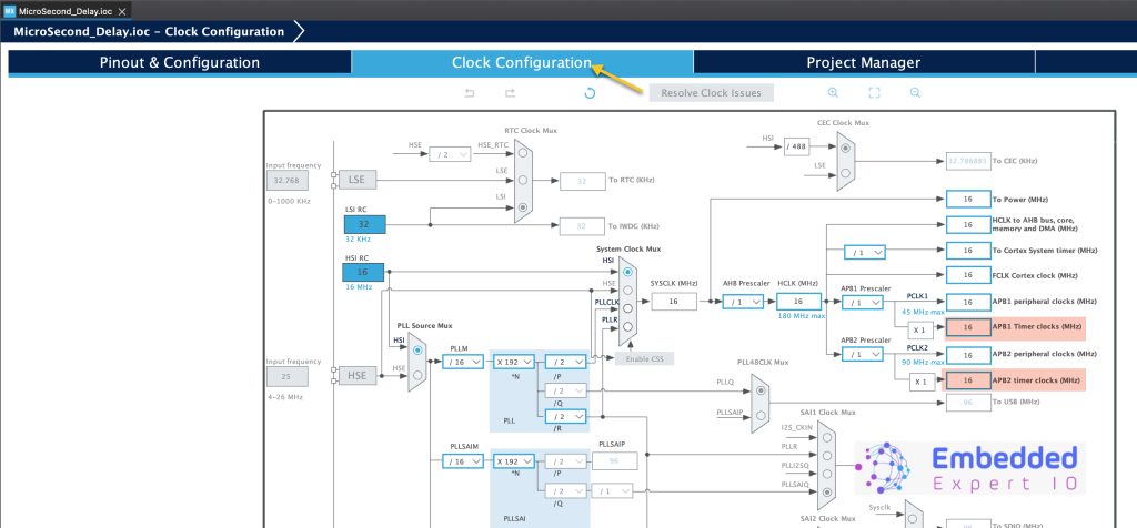
Notice timers clock. Since STM32F4 has default frequency of 16MHz, hence timers frequency is 16MHz.
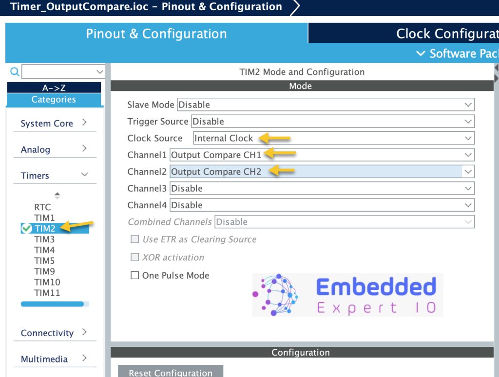
Next, from Pinout and Configuration, select timers, then the desired timer (TIM2 in the case) as following:
- Clock Source to Internal Clock.
- Channel 1 to Output Compare CH1
- Channel 2 to Output Compare CH2.
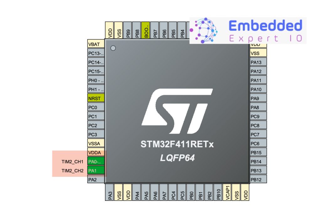
This will set PA0 and PA1 for timer CH1 and CH2 as following:
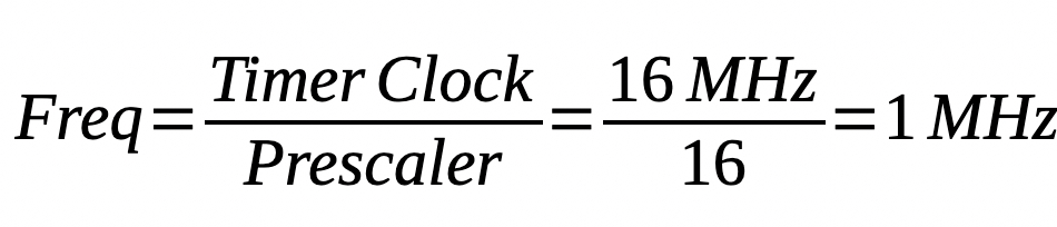
Since we already know that timer frequency is 16MHz, we can use prescaler to 16 to get 1MHz as following:
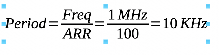
With Counter Period of 100, this will further reduce the speed from 1MHz to 10KHz as following:
However, in this guide, we shall use 1000-1 which will give timer period of 1ms (1KHz).
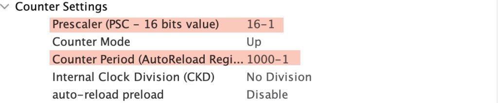
The reason behind the -1 since MCU start counts from 0 rather than 1, hence it needs to be included.
Next, we shall configure the channels:
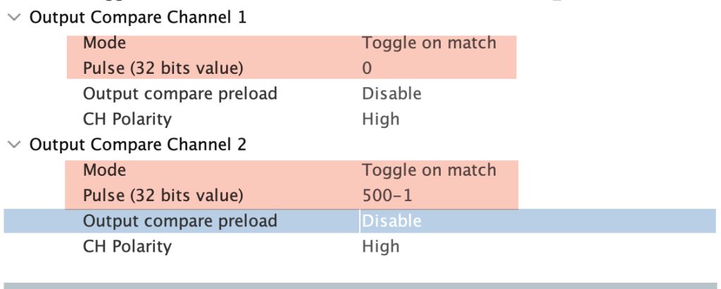
Configure Channel 1 as following:
- Mode Toggle on match.
- Pulse to 0.
Configure Channel 2 as following:
- Mode to toggle Mode.
- Pulse to 500-1.
Thats all for the configuration. Save the project and this will generate the project.
3. Firmware Development:
Once the project has been generated, main.c will be opened.
In main.c source file, in user code begin 2 in main function, we shall start both channel as OC as following:
  HAL_TIM_OC_Start(&htim2, TIM_CHANNEL_1);
  HAL_TIM_OC_Start(&htim2, TIM_CHANNEL_2);
The function HAL_TIM_OC_Start takes two arguments:
- Instant to the timer which is htim2 in this case.
- timer channel, which is TIM_CHANNEL_1 and 2 in this case.
Save the project, build and run it on your board as following:

4. Results:
Using either logic analyzer or oscilloscope, you should get the following:
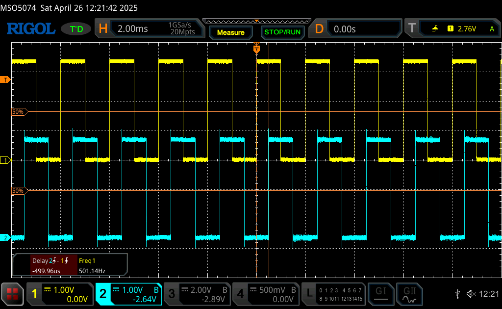
The frequency is 500Hz, which is as expected since the mode is to toggle on match which gives half the frequency of the timer.
The delay between rising edge is 500uS which is same as set in the configuration.
Happy coding 😉
Add Comment