In previous guides, we looked at TIM2 of STM32 to generate delay, interrupts, PWM and how to use PWM to fade LED and control servo motors. In this guide, we shall cover how to use TIM2 of STM32 to read shaft encoder.
We will cover the following:
- What is encoder
- Required parts and connection
- Configure pins and timer to read encoder
- Download the code
- Demo
1.1 What is encoder:
A rotary encoder, also called a shaft encoder, is an electro-mechanical device that converts the angular position or motion of a shaft or axle to analog or digital output signals.
Rotary encoders are used in a wide range of applications that require monitoring or control, or both, of mechanical systems, including industrial controls, robotics, photographic lenses, computer input devices such as optomechanical mice and trackballs, controlled stress rheometers, and rotating radar platforms.
1.2 Encoder types:
- Mechanical: Also known as conductive encoders. A series of circumferential copper tracks etched onto a PCB is used to encode the information via contact brushes sensing the conductive areas. Mechanical encoders areeconomical but susceptible to mechanical wear. They are common in human interfaces such as digital multimeters
- Optical: This uses a light shining onto a photodiode through slits in a metal or glass disc. Reflective versions also exist. This is one of the most common technologies. Optical encoders are very sensitive to dust.
- On-Axis Magnetic: This technology typically uses a specially magnetized 2 pole neodymium magnet attached to the motor shaft. Because it can be fixed to the end of the shaft, it can work with motors that only have 1 shaft extending out of the motor body. The accuracy can vary from a few degrees to under 1 degree. Resolutions can be as low as 1 degree or as high as 0.09 degree (4000 CPR, Count per Revolution). Poorly designed internal interpolation can cause output jitter, but this can be overcome with internal sample averaging.
- Off-Axis Magnetic: This technology typically employs the use of rubber bonded ferrite magnets attached to a metal hub. This offers flexibility in design and low cost for custom applications. Due to the flexibility in many off axis encoder chips they can be programmed to accept any number of pole widths so the chip can be placed in any position required for the application. Magnetic encoders operate in harsh environments where optical encoders would fail to work. (from wikipedia)
1.3 Encoder Output:
In out case, the encoder shall generate pulses on both DT and CLK lines in a certain manner that can be read by the timer of stm32. In the figure below, is the output from shaft encoder when rotating clockwise. Clk is yellow and DT is Blue.
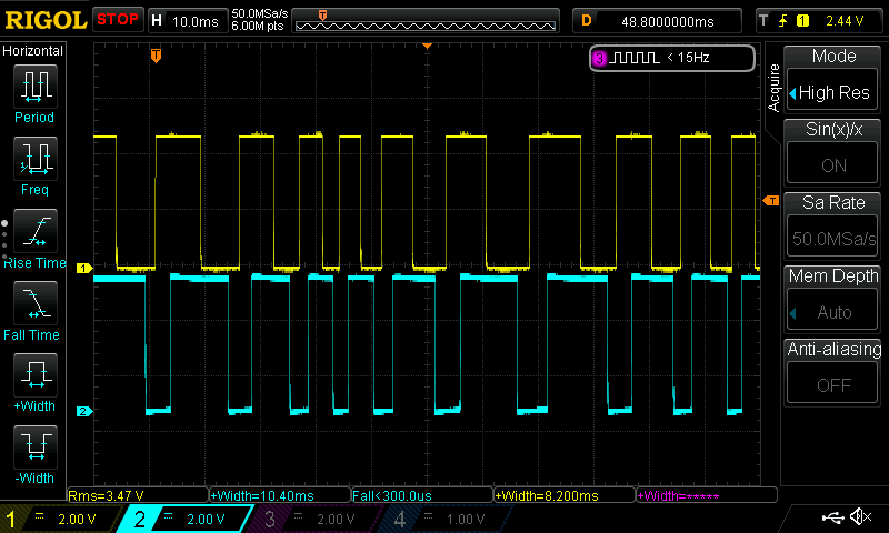
When the shaft encoder rotate clockwise, CLK like pulled high first then DT line which indicates there is rotation.
When the counter clock rotation occurs, the DT line is pulled high first then the CLK line.

2.1 Required Parts:
In this guide, we will need the following:
- STM32F411Re Nucleo-64.
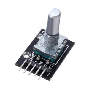
- Shaft encoder (4 wire).
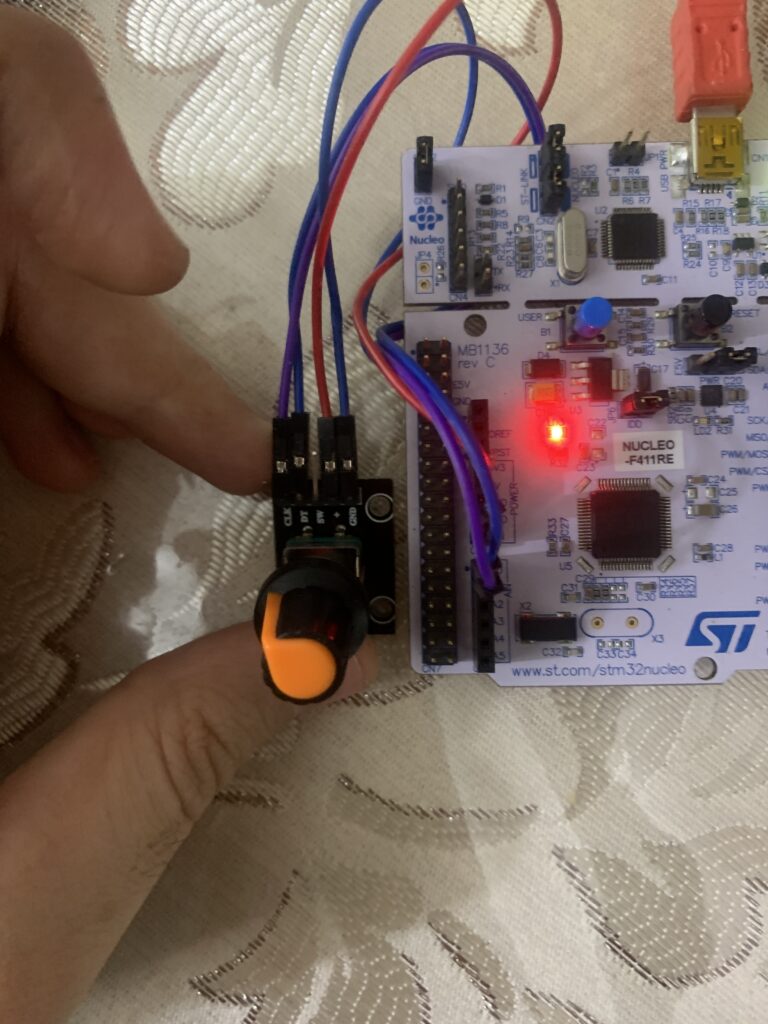
2.2 Connection:
The connection is as following
| Encoder Pin | STM32F411-Nucleo64 Pin |
| GND | GND |
| + | 3V3 |
| DT | PA0 |
| CLK | PA1 |
3.1 Pin Configuration:
For pin configuration, it will be the same as timer guide (here).
RCC->AHB1ENR|=RCC_AHB1ENR_GPIOAEN;
GPIOA->MODER|=(1<<1)|(1<<3);
GPIOA->AFR[0]|=(1<<0)|(1<<4);
3.2 Timer Configuration:
In order to config the timer to read encoder, the following steps are required:
First we start by enabling clock access to TIM2 of stm32
RCC->APB1ENR|=RCC_APB1ENR_TIM2EN;
Then set the maximum value for timer to count as following
TIM2->ARR = max_value;
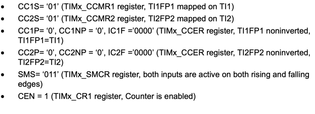
then set bot CC1S and CC2S as following
TIM2->CCMR1 |= (TIM_CCMR1_CC1S_0 | TIM_CCMR1_CC2S_0 );
Set both channel to input as following
TIM2->CCER &= ~(TIM_CCER_CC1P | TIM_CCER_CC2P);
Now, we tell the TIM to operate in encoder mode as following
TIM2->SMCR |= TIM_SMCR_SMS_0 | TIM_SMCR_SMS_1;
Finally enable timer as following
TIM2->CR1 |= TIM_CR1_CEN ;
To read the encoder just read the current timer counter as following
uint32_t read_encoder(void)
	{

		return TIM2->CNT;

	}
4.1 Code:
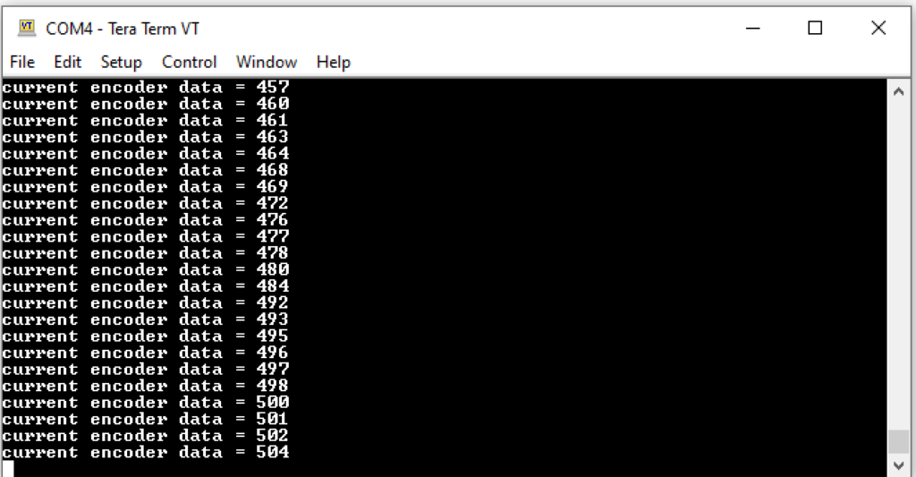
You can download the entire project from here (it uses UART to display the results)
After you compile the code, upload to your board. Open your favourite terminal (TeraTerm in my case) and set the baud rate to 9600 rotate the encoder and you shall get this
4 Comments
Good afternoon. I don’t understand how the microprocessor frequency is set in this code and why the speed of usart is set to 9600 at 16 MHz, if the processor frequency is not explicitly set anywhere. how to change for example not 115200.
By default, STM32F4xx runs at 16MHz.
This is mentioned in the reference manual of STM32F4xx
I am trying to make this code work with Arduino giga R1 which has STM32h7 processor, but the counter doesn’t read anything even though i have crosschecked everything.(ENCODER is working fine). DO you have any suggestions?
Hi,
use HAL API with H7:
https://blog.embeddedexpert.io/?p=2396
Add Comment