
In this article, we shall look at the dth11 temperature and humidity sensor and how does it work and interface it with STM32F4 Nucleo-64 board.
In this guide, we shall cover the following:
- DHT11
- Connection
- Code
- Demo
1. DHT11:
The DHT11 Temperature & Humidity Sensor features a temperature & humidity sensor complex with a calibrated digital signal output. By using the exclusive digital-signal-acquisition technique and temperature & humidity sensing technology, it ensures high reliability and excellent long-term stability. This sensor includes a resistive-type humidity measurement component and an NTC temperature measurement component, and connects to a high- performance 8-bit microcontroller, offering excellent quality, fast response, anti-interference ability and cost-effectiveness.
Each DHT11 element is strictly calibrated in the laboratory that is extremely accurate on humidity calibration. The calibration coefficients are stored as programmes in the OTP memory, which are used by the sensor’s internal signal detecting process. The single-wire serial interface makes system integration quick and easy. Its small size, low power consumption and up-to-20 meter signal transmission making it the best choice for various applications, including those most demanding ones. The component is 4-pin single row pin package. It is convenient to connect and special packages can be provided according to users’ request.
HOW THE DHT11 MEASURES HUMIDITY AND TEMPERATURE
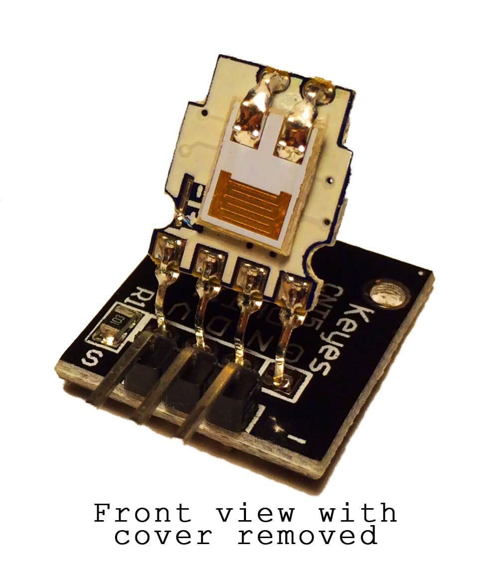
The DHT11 detects water vapor by measuring the electrical resistance between two electrodes. The humidity sensing component is a moisture holding substrate with electrodes applied to the surface. When water vapor is absorbed by the substrate, ions are released by the substrate which increases the conductivity between the electrodes. The change in resistance between the two electrodes is proportional to the relative humidity. Higher relative humidity decreases the resistance between the electrodes, while lower relative humidity increases the resistance between the electrodes.
The DHT11 measures temperature with a surface mounted NTC temperature sensor (thermistor) built into the unit.
With the plastic housing removed, you can see the electrodes applied to the substrate:
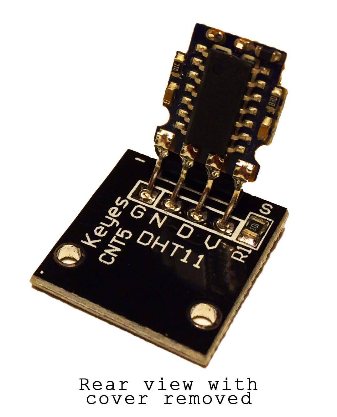
An IC mounted on the back of the unit converts the resistance measurement to relative humidity. It also stores the calibration coefficients, and controls the data signal transmission between the DHT11 and the Arduino:
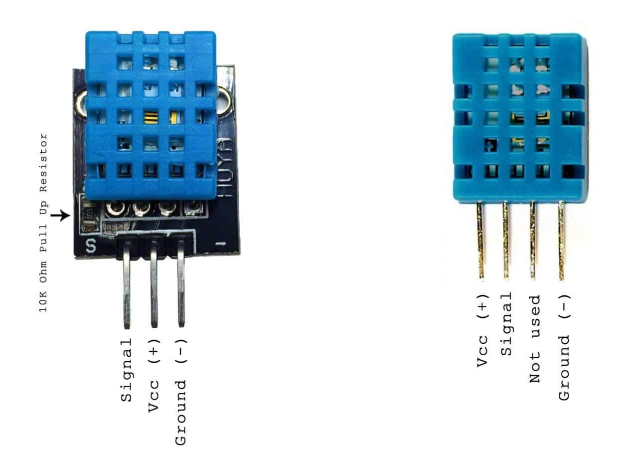
The DHT11 uses just one signal wire to transmit data to the Arduino. Power comes from separate 5V and ground wires. A 10K Ohm pull-up resistor is needed between the signal line and 5V line to make sure the signal level stays high by default (see the datasheet for more info).
There are two different versions of the DHT11 you might come across. One type has four pins, and the other type has three pins and is mounted to a small PCB. The PCB mounted version is nice because it includes a surface mounted 10K Ohm pull up resistor for the signal line. Here are the pin outs for both versions:
Technical Details
- Low cost
- 3 to 5V power and I/O
- 2.5mA max current use during conversion (while requesting data)
- Good for 20-80% humidity readings with 5% accuracy
- Good for 0-50°C temperature readings ±2°C accuracy
- No more than 1 Hz sampling rate (once every second)
- Body size 15.5mm x 12mm x 5.5mm
- 4 pins with 0.1″ spacing
Since the accuracy of the sensor is not that great, it is mostly used for temperature and humidity indicator in home application.
2. Connection:
In this guide, we will need the following:
- STM32F411RE-Nucleo-64
- DHT11 Sensor
- 0.96″ OLED display
- Small breadboard
- Hookup wires
The connection shall be as shown in the image below
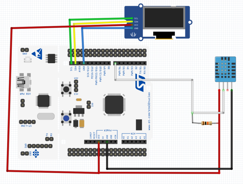
In my case the module used has built-in pull resistor. Hence, no need to connect external one.
3. Code:
We need the following:
3.1 Delay in milliseconds:
We start off by creating delay.c and delay.h
The code for delay in milliseconds inside delay.c as following:
#include "delay.h"
#include "stm32f4xx.h"                  // Device header


volatile uint64_t ms,rms;
void systick_init_ms(uint32_t freq)
	{
	__disable_irq();
	SysTick->LOAD=(freq/1000)-1;
	SysTick->VAL=0;
	SysTick->CTRL=7; //0b00000111;
	__enable_irq();
}

uint64_t millis(void)
	{
	__disable_irq();
	rms=ms; //store current ms in rms
	__enable_irq();
	return rms;
	}

void SysTick_Handler(void){
ms++;
}

void delay(uint32_t delay)
	{

		uint64_t start=millis();
	do
		{}while(millis()-start!=delay);
	}
for delay.h
#ifndef __delay__H__
#define __delay__H__


#include <stdint.h>
uint64_t millis(void);
void systick_init_ms(uint32_t freq);
void delay(uint32_t delay);
#endif
3.2 Microseconds timer:
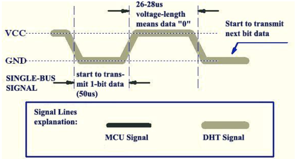
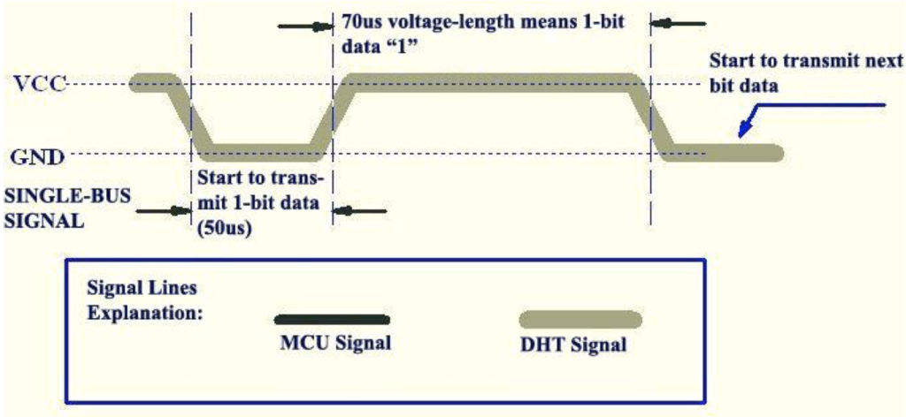
In order to interface DHT11 with STM32, we need to measure how long the signal stayed high in microseconds as shown two figures below:
Hence, we can create two files named micros.h and micros.c
In micros, we start off by declaring function for initialising micros which takes bus frequency as argument
void micros_init(uint32_t freq)
Within the function, we enable clock access to timer3
RCC->APB1ENR|=RCC_APB1ENR_TIM3EN; //enable timer3 clock access
Set the prescaler
TIM3->PSC=freq-1; //100 000 000 Hz / 1 00 = 1 000 000 Hz
Reset the counter
TIM3->CNT=0;
Enable counter as following:
TIM3->CR1|=TIM_CR1_CEN;
We also need two extra function:
- Reset the microseconds counter
void reset_micros(void)
	{
	TIM3->CR1&=~TIM_CR1_CEN;
	TIM3->CNT=0;
	TIM3->CR1|=TIM_CR1_CEN;
	}
Return the current timer value
uint32_t micros(void)
	{
	return TIM3->CNT;
	}
In micros.h
#ifndef __micros__h
#define __micros__h
#include "stdint.h"


void micros_init(uint32_t freq);
void reset_micros(void);
uint32_t micros(void);


#endif
3.3 DHT read:
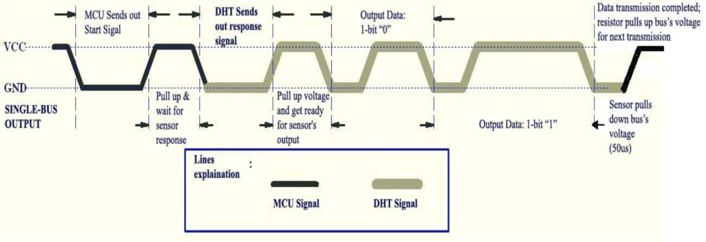
In order to read DHT11, the mcu must send low signal for 18 milliseconds as shown in the figure below
We declare read_dht which returns int8_t and takes no argument
int8_t read_dht(void)
Inside the read function. we start by enabling clock access to GPIOA
RCC->AHB1ENR|=RCC_AHB1ENR_GPIOAEN;
declare some local required variables
	uint8_t bits[5];
	uint8_t cnt = 7;
	uint8_t idx = 0;
	for (int i=0; i< 5; i++) {bits[i] = 0;}
Set PA8 to output and set it to low
	GPIOA->MODER|=GPIO_MODER_MODE8_0;
	GPIOA->ODR&=~GPIO_ODR_OD8;
	delay(18);
Set PA8 to high
GPIOA->ODR|=GPIO_ODR_OD8;
reset micros counter and set PA8 to input
	reset_micros();
	uint32_t start=micros();
	for(int i=0;i<1000;i++); //wait a littl bit
	GPIOA->MODER&=~GPIO_MODER_MODE8_0;
Then we check for the response, if there is no response, return -2 as error code
	unsigned int loopCnt = 1000000;

	while(!(GPIOA->IDR & GPIO_IDR_ID8)){if (loopCnt-- == 0) return -2;}
	loopCnt = 10000;
	while((GPIOA->IDR & GPIO_IDR_ID8)){if (loopCnt-- == 0) return -2;}
Since dht11 sends 40-bits of data, we can start acquire them
	for (int i=0; i<40; i++)
  {
    loopCnt = 100000;
    while(!(GPIOA->IDR & GPIO_IDR_ID8))
		{if (loopCnt-- == 0) return -2;}

    unsigned long t = micros();

    loopCnt = 1000000;
    while((GPIOA->IDR & GPIO_IDR_ID8))
      if (loopCnt-- == 0)
			{return -2;}

    if ((micros() - t) > 40) bits[idx] |= (1 << cnt);
    if (cnt == 0)
    {
      cnt = 7;
      idx++;
    }
    else cnt--;
  }

	temp= bits[2];
	hum= bits[0];
	uint8_t sum = bits[0] + bits[2];
  if (bits[4] != sum)
	{return -1;}

  return 0;

	}
Then we can use functions to return the temperature and humidity
uint8_t read_temp(){return temp;}
uint8_t read_hum(){return hum;}
In main.c
#include "oled.h"
#include "dht.h"
#include "micros.h"
#include "stdio.h"
#include "fonts.h"
extern void SysClockConfig(void);
uint8_t temperature,humidity;
int8_t error;

char data[20];

int main(void)
	{
		SysClockConfig();
		systick_init_ms(100000000);
		micros_init(100);
		SSD1306_Init();
		SSD1306_GotoXY (0,0);
		SSD1306_Puts ("DHT11", &Font_11x18, 1);
		SSD1306_GotoXY (0,20);
		SSD1306_Puts ("STM32", &Font_11x18, 1);
		SSD1306_UpdateScreen(); //display
		delay(3000);
		SSD1306_Clear();

		while(1)
			{
				error=read_dht();
				temperature=read_temp();
				humidity=read_hum();
				sprintf(data,"temp=%u C",temperature);
				SSD1306_GotoXY (0,0);
				SSD1306_Puts (data, &Font_11x18, 1);
				sprintf(data,"hum=%u C",humidity);
				SSD1306_GotoXY (0,20);
				SSD1306_Puts (data, &Font_11x18, 1);
				SSD1306_UpdateScreen(); //display
				delay(1000);
			}
	}
You may download the entire project from here:
4. Demo:
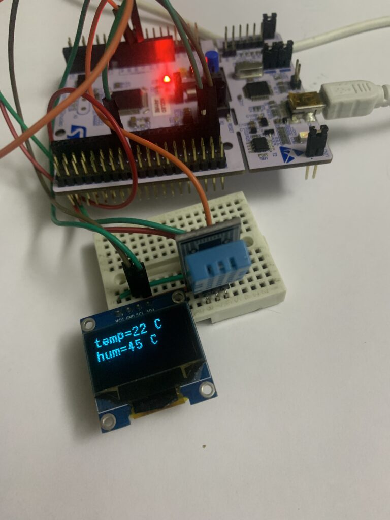
After compile, uploading the code to the board, you should get this
Happy coding 🙂
2 Comments
the program is not working for me can you please help.
Wait for a revised version.
Add Comment