This tutorial teaches you how to interface an OLED display with STM32F411. In this article, we will show how to use SSD1306 0.96 inch I2C OLED with STM32F411-Nucleo64. This modern organic light emitting diode based display can be used to write simple text, scrolling text, display bitmap images, draw different shapes, digital and analog clock. Firstly, we will see how to connect it with STM32F411. In the end, we will see programming examples of STM32F411 with SSD1306 0.96 inch I2C OLED using Keil uvision for ARM.
In this guide, we will cover the following:
- SSD1306 OLED display
- Interface with STM32F4
- Initializing sequence
- Basic function to display text
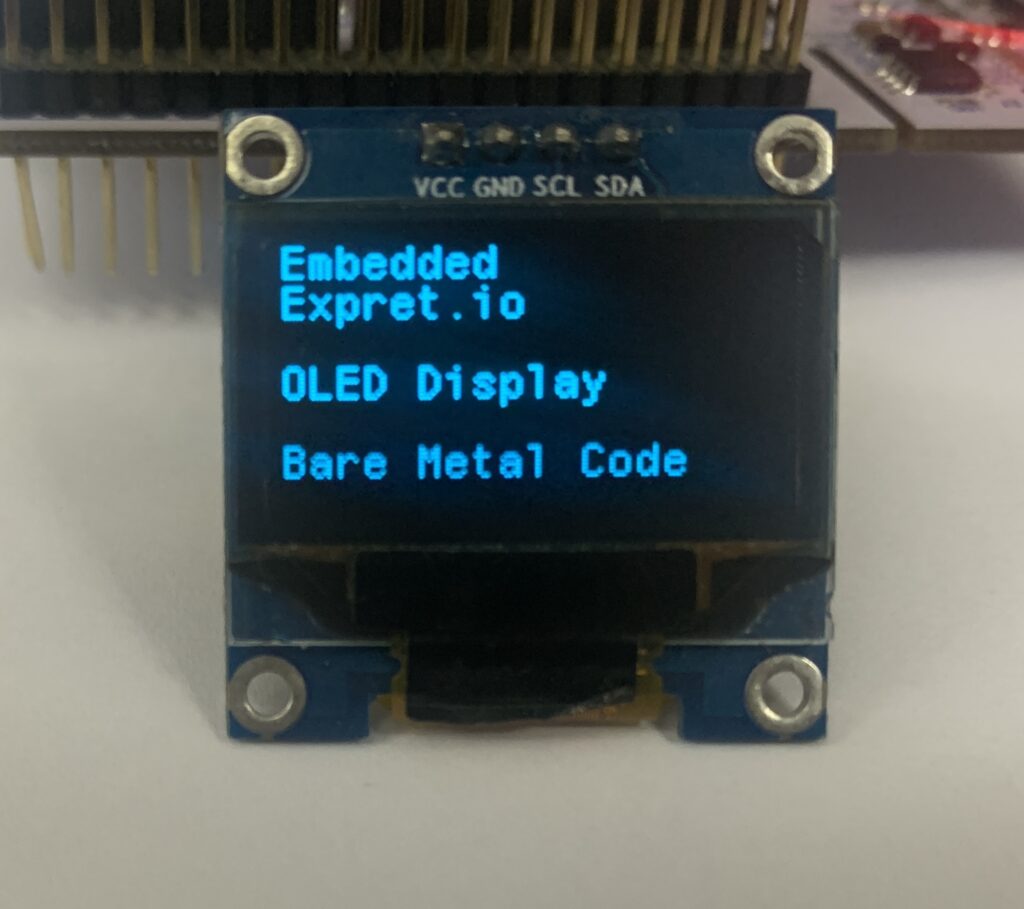
- Demo
1. SSD1306 OLED Display:
Do you want to give a perfect look to your microcontroller project which traditional liquid crystal displays (LCDs) do not promise? In this case, OLED displays will be the best choice for you. Because they offer a good view angle and pixel density which makes it the perfect choice for graphics display projects at low cost.
SSD1306 OLED Types
There are different types of OLED displays available in the market. But the common thing in most displays is the SSD1306 CMOS OLED driver controller. The main component of OLED is an SSD1306 controller which is used to communicate with microcontrollers, such as TM4C123 Tiva Launchpad or STM32F4, using either SPI or I2C communication. But usually, I2C communication is preferred because it requires only two wires to communicate with STM32F411.
I2C OLED Display
These displays come in different colors, sizes and shapes. In this tutorial, we will use an I2C based OLED display having size of 128×64 as shown in the figure below. But the good thing is programming doesn’t change much with the change of OLED size and color.
The following picture shows the pin wiring of the OLED display. As you can see from its pinout diagram, it consists of four pins such as Vcc, GND, SCL, and SDA. Vcc and GND pins are used to power OLED displays and the operating voltage range is between 3.3-5V. That means we can easily power it from the same source and connect directly with microcontrollers
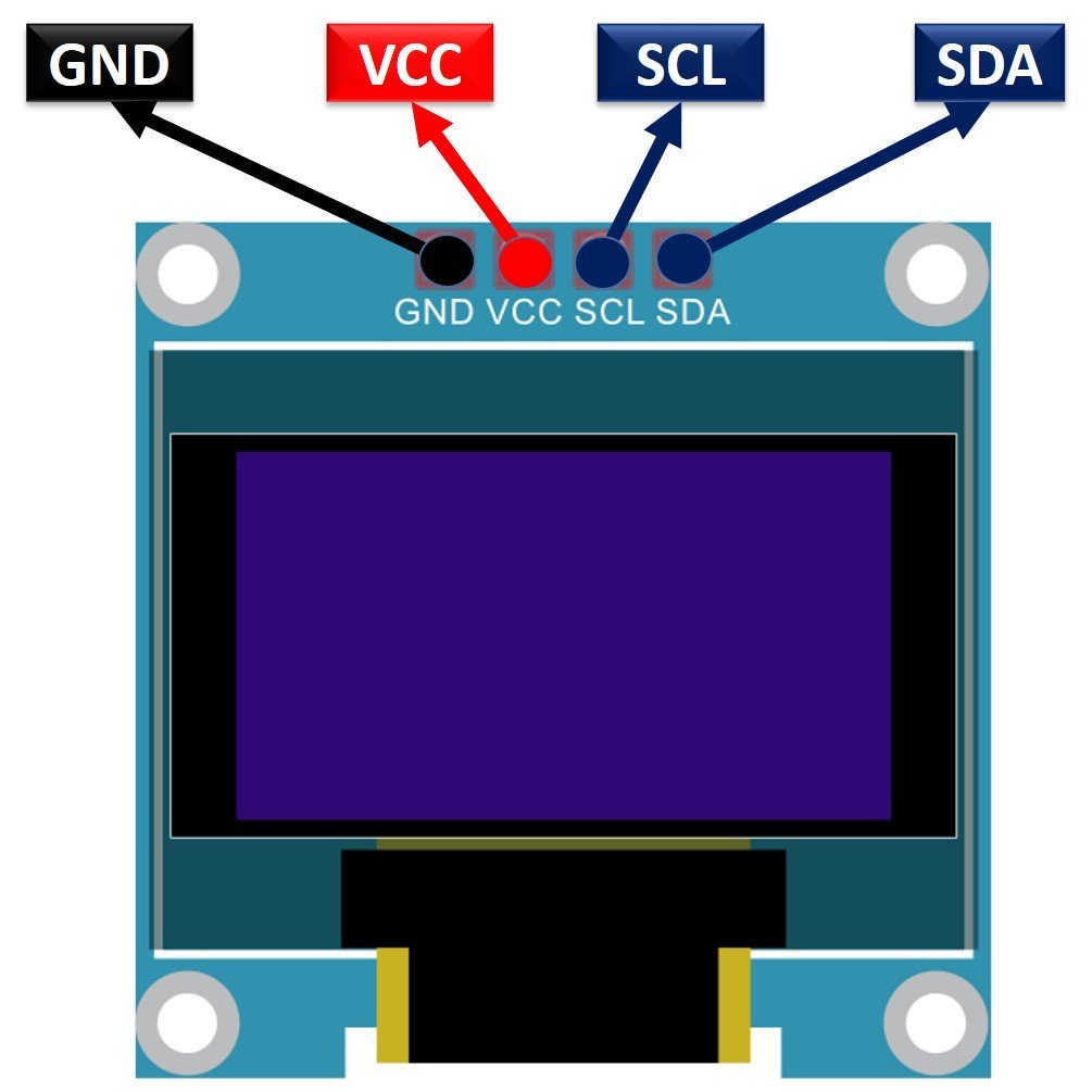
SCL and SDA are the serial clock and serial data pins respectively. They connect with I2C pins of microcontrollers (STM32F411) to perform I2C communication.
2.Interface with STM32F411-Nucleo64
Before diving into the interfacing diagram of OLED with STM32F411, we need to understand the power supply and current consumption requirement of OLED. By knowing about voltage range and current requirement, we will determine that either we can drive this display directly with STM32F411 or we need to connect any interfacing circuitry?
According to the datasheet of SDS1306 OLED display, the operating voltage range is between 3.3-5V and maximum current requirement is 20mA. That means we can directly interface the OLED display with STM32F411. Because the STM32F411 Nucleo64 development board has onboard 3.3V power source signal and GPIO pins can sink and source upto 20mA current. Hence, we can directly interface OLED with STM32F411.
Interfacing Diagram
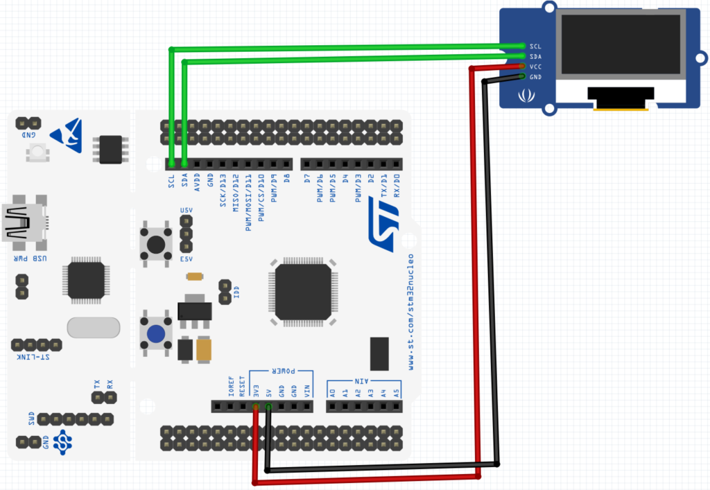
To interface an OLED display with STM32F411, we use four pins only such as Vcc, GND, and I2C communication pins such as SCL and SDA. STM32F411 microcontroller which comes with STM32F411 has three built-in I2C modules such as I2C1, I2C2 and I2C3.
In this tutorial, we will use the I2C1 module of STM32F411 to communicate with OLED. For I2C1 port, PB9 and PB8 (GPIOB) are SDA and SCL pins respectively. Now make connection with STM32F411 and OLED display according to the diagram shown below:
| STM32F411 | SSD1306 OLED |
|---|---|
| PB8 /I 2C1 | SCL |
| PB9 / I2C1 | SDA |
| 3.3V | Vcc |
| GND | GND |
3. Initializing Sequence:
Since the display uses I2c, we need to initialize the I2C1 in fast mode (included in the code)
Before we start, we need to define some macros that will help up
 //#define SSD1306_I2C_ADDR 0x3C
/* Write command */
#define SSD1306_WRITECOMMAND(command)      i2c_writeByte(SSD1306_I2C_ADDR, 0x00, (command))
/* Write data */
#define SSD1306_WRITEDATA(data)            i2c_writeByte(SSD1306_I2C_ADDR, 0x40, (data))
/* Absolute value */
#define ABS(x)   ((x) > 0 ? (x) : -(x))
We need also for some private variable as following:
/* SSD1306 data buffer */
static char SSD1306_Buffer[SSD1306_WIDTH * SSD1306_HEIGHT / 8];

/* Private SSD1306 structure */
typedef struct {
	uint16_t CurrentX;
	uint16_t CurrentY;
	uint8_t Inverted;
	uint8_t Initialized;
} SSD1306_t;

/* Private variable */
static SSD1306_t SSD1306;


#define SSD1306_RIGHT_HORIZONTAL_SCROLL              0x26
#define SSD1306_LEFT_HORIZONTAL_SCROLL               0x27
#define SSD1306_VERTICAL_AND_RIGHT_HORIZONTAL_SCROLL 0x29
#define SSD1306_VERTICAL_AND_LEFT_HORIZONTAL_SCROLL  0x2A
#define SSD1306_DEACTIVATE_SCROLL                    0x2E // Stop scroll
#define SSD1306_ACTIVATE_SCROLL                      0x2F // Start scroll
#define SSD1306_SET_VERTICAL_SCROLL_AREA             0xA3 // Set scroll range

#define SSD1306_NORMALDISPLAY       0xA6
#define SSD1306_INVERTDISPLAY       0xA7
The initializing sequence is as following:
void ssd1306_I2C_Init() {
//delay
	uint32_t p = 250000;
	while(p>0)
		p--;

}

uint8_t SSD1306_Init(void) {

	/* Init I2C */
	i2c_init();
	ssd1306_I2C_Init();


	/* A little delay */
	uint32_t p = 2500;
	while(p>0)
		p--;

	/* Init LCD */
	SSD1306_WRITECOMMAND(0xAE); //display off
	SSD1306_WRITECOMMAND(0x20); //Set Memory Addressing Mode
	SSD1306_WRITECOMMAND(0x10); //00,Horizontal Addressing Mode;01,Vertical Addressing Mode;10,Page Addressing Mode (RESET);11,Invalid
	SSD1306_WRITECOMMAND(0xB0); //Set Page Start Address for Page Addressing Mode,0-7
	SSD1306_WRITECOMMAND(0xC8); //Set COM Output Scan Direction
	SSD1306_WRITECOMMAND(0x00); //---set low column address
	SSD1306_WRITECOMMAND(0x10); //---set high column address
	SSD1306_WRITECOMMAND(0x40); //--set start line address
	SSD1306_WRITECOMMAND(0x81); //--set contrast control register
	SSD1306_WRITECOMMAND(0xFF);
	SSD1306_WRITECOMMAND(0xA1); //--set segment re-map 0 to 127
	SSD1306_WRITECOMMAND(0xA6); //--set normal display
	SSD1306_WRITECOMMAND(0xA8); //--set multiplex ratio(1 to 64)
	SSD1306_WRITECOMMAND(0x3F); //
	SSD1306_WRITECOMMAND(0xA4); //0xa4,Output follows RAM content;0xa5,Output ignores RAM content
	SSD1306_WRITECOMMAND(0xD3); //-set display offset
	SSD1306_WRITECOMMAND(0x00); //-not offset
	SSD1306_WRITECOMMAND(0xD5); //--set display clock divide ratio/oscillator frequency
	SSD1306_WRITECOMMAND(0xF0); //--set divide ratio
	SSD1306_WRITECOMMAND(0xD9); //--set pre-charge period
	SSD1306_WRITECOMMAND(0x22); //
	SSD1306_WRITECOMMAND(0xDA); //--set com pins hardware configuration
	SSD1306_WRITECOMMAND(0x12);
	SSD1306_WRITECOMMAND(0xDB); //--set vcomh
	SSD1306_WRITECOMMAND(0x20); //0x20,0.77xVcc
	SSD1306_WRITECOMMAND(0x8D); //--set DC-DC enable
	SSD1306_WRITECOMMAND(0x14); //
	SSD1306_WRITECOMMAND(0xAF); //--turn on SSD1306 panel


	SSD1306_WRITECOMMAND(SSD1306_DEACTIVATE_SCROLL);

	/* Clear screen */
	SSD1306_Fill(SSD1306_COLOR_BLACK);

	/* Update screen */
	SSD1306_UpdateScreen();

	/* Set default values */
	SSD1306.CurrentX = 0;
	SSD1306.CurrentY = 0;

	/* Initialized OK */
	SSD1306.Initialized = 1;

	/* Return OK */
	return 1;
}
4. Basic function:
In order to display some text we need the following three function:
- Go to specific xy position
void SSD1306_GotoXY(uint16_t x, uint16_t y) {
	/* Set write pointers */
	SSD1306.CurrentX = x;
	SSD1306.CurrentY = y;
}- Put characters:
char SSD1306_Puts(char* str, FontDef_t* Font, SSD1306_COLOR_t color) {
	/* Write characters */
	while (*str) {
		/* Write character by character */
		if (SSD1306_Putc(*str, Font, color) != *str) {
			/* Return error */
			return *str;
		}

		/* Increase string pointer */
		str++;
	}

	/* Everything OK, zero should be returned */
	return *str;
}- Finally update the display:
void SSD1306_UpdateScreen(void) {
	uint8_t m;

	for (m = 0; m < 8; m++) {
		SSD1306_WRITECOMMAND(0xB0 + m);
		SSD1306_WRITECOMMAND(0x00);
		SSD1306_WRITECOMMAND(0x10);

		/* Write multi data */
		ssd1306_I2C_WriteMulti(SSD1306_I2C_ADDR, 0x40, &SSD1306_Buffer[SSD1306_WIDTH * m], SSD1306_WIDTH);
	}
}
You may download the code from here which includes horse animation also from here:
5. Demo:
Happy coding 🙂
12 Comments
Hi.
Could you explain how to use 8 bit format font instead of 32 bit format?
Or could you indicate wich program do you use to make your fonts?
Thank you.
This might be helpful.
https://blog.embeddedexpert.io/?p=488
can you do the same using stm32f103rct6 mc
yes you can.
However, you need to modify the i2c driver.
Is it possible to rotate the display 180 degrees?
Hi,
The hardware doesn’t support rotation.
You need to do this using software.
Is there anyone managed to make some functions to flipt the screen?
Hi,
To flip the SSD1306 OLED display by 180 degrees, you can send one of the following commands:
1. **For Normal Display (default orientation):**
“`c
0xA1 // Set Segment Re-map (flip horizontally)
0xC8 // Set COM Output Scan Direction (flip vertically)
“`
2. **For Flipped Display (180 degrees rotation):**
“`c
0xA0 // Set Segment Re-map (normal direction)
0xC0 // Set COM Output Scan Direction (normal direction)
“`
This will change the orientation of the display to flip it 180 degrees.
Hi I am using the STM32F446RE MCU NUCLEO-F446RE and I am getting a lot of errors. It happens when declaring uint16_t, SSD1306_WRITECOMMAND, etc.
Hi,
make sure to adapt the OLED driver to reflect the I2C driver and also include stdint header file.
Hey man! is there a way I can contact you? I’m having trouble with my OLED on my stm32F103RBT6 and the code runs good but it doesn’t show anything on my scree.
Hi,
use this i2c scanner to get the address of the OLED:
https://blog.embeddedexpert.io/?p=1493
Add Comment