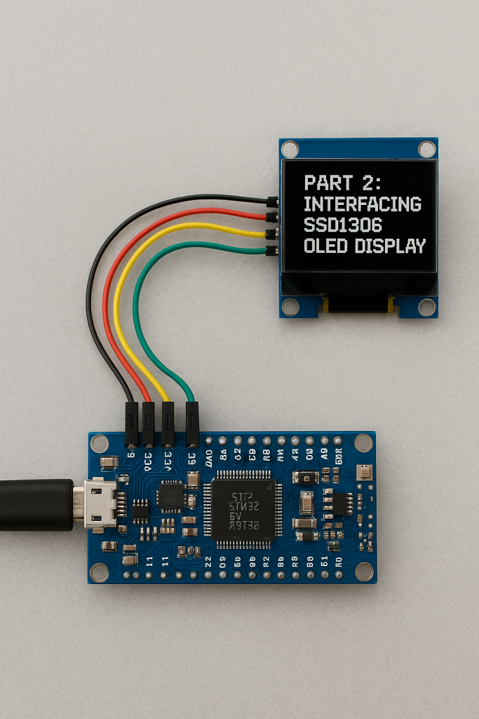
In this part, we will use the U8g2 library to interface the popular SSD1306 OLED display with STM32. This will demonstrate how to initialize the display and render text and graphics through U8g2.
In this guide, we shall cover the following:
- Adding the U2G8 library to the project.
- Developing delay, GPIO and communication callback.
- Developing the firmware.
- Results.
5. Adding U8G2 Library To The Project:
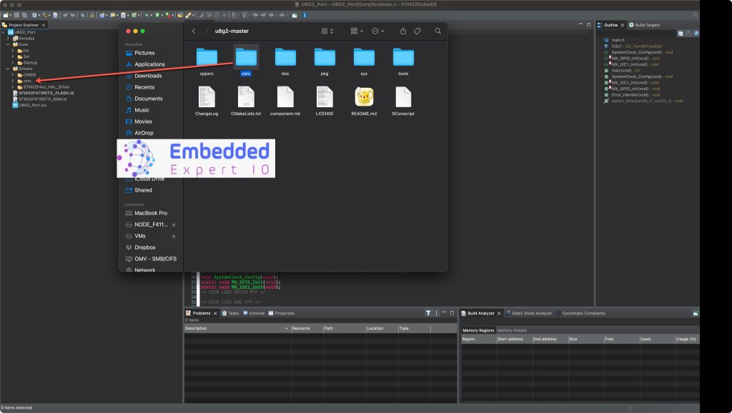
After downloading the library from the github repository, extract it.
Open the extract is completed, copy csrc folder to the driver folder as follows:
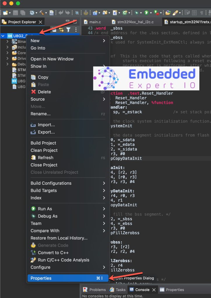
Next, right click on the project and click on properties:
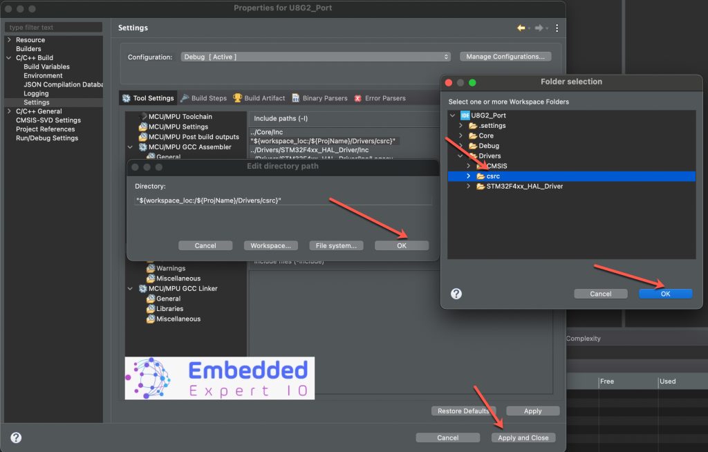
Next, open the project properties -> C/C++ Build -> Settings -> GCC Compiler -> Include Path and click add button to add the folder path here.
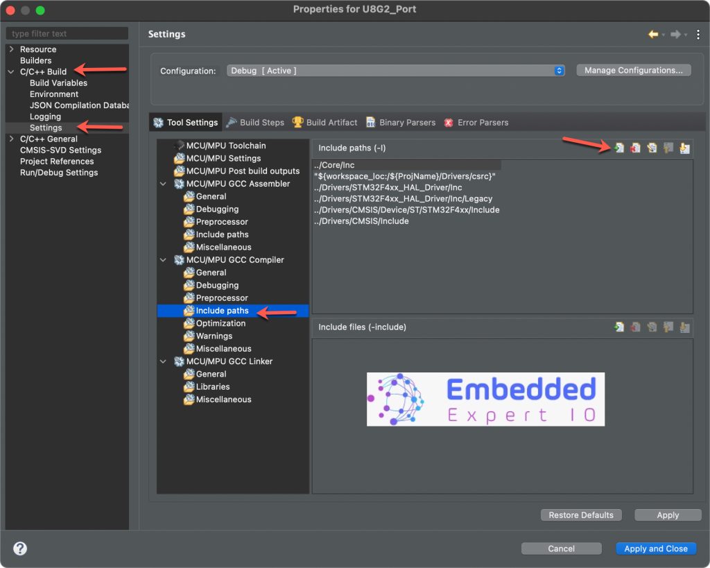
Add the path as follows and click on Apply and Close.
Now, the library has been added and can be compiled without any issue.
6. Developing Delay, GPIO and Communication Callback Function:
The “uC specific” GPIO and Delay callback
GPIO and Delay callback takes care of all the messages regarding the GPIO and Delay.
The Delay messages might include the delay needed for the display (mostly in millis) or the delay needed to generate the SPI or I2C clocks (mostly in nano or micro) in case the software SPI or I2C is implemented.
The GPIO messages include the setting and resetting of the GPIO pins used for interfacing the display. These GPIO pins might include the data pins (D0 D1 D2 etc.. in parallel mode) or the control pins (CS RST DC in SPI mode).
GPIO and Delay callback function as follows:
uint8_t u8x8_gpio_and_delay_template(u8x8_t *u8x8, uint8_t msg, uint8_t arg_int, void *arg_ptr)
{
  switch(msg)
  {
    case U8X8_MSG_GPIO_AND_DELAY_INIT:	// called once during init phase of u8g2/u8x8
      break;							// can be used to setup pins
    case U8X8_MSG_DELAY_NANO:			// delay arg_int * 1 nano second
      break;
    case U8X8_MSG_DELAY_100NANO:		// delay arg_int * 100 nano seconds
      break;
    case U8X8_MSG_DELAY_10MICRO:		// delay arg_int * 10 micro seconds
      break;
    case U8X8_MSG_DELAY_MILLI:			// delay arg_int * 1 milli second
      break;
    case U8X8_MSG_DELAY_I2C:				// arg_int is the I2C speed in 100KHz, e.g. 4 = 400 KHz
      break;							// arg_int=1: delay by 5us, arg_int = 4: delay by 1.25us
    case U8X8_MSG_GPIO_D0:				// D0 or SPI clock pin: Output level in arg_int
    //case U8X8_MSG_GPIO_SPI_CLOCK:
      break;
    case U8X8_MSG_GPIO_D1:				// D1 or SPI data pin: Output level in arg_int
    //case U8X8_MSG_GPIO_SPI_DATA:
      break;
    case U8X8_MSG_GPIO_D2:				// D2 pin: Output level in arg_int
      break;
    case U8X8_MSG_GPIO_D3:				// D3 pin: Output level in arg_int
      break;
    case U8X8_MSG_GPIO_D4:				// D4 pin: Output level in arg_int
      break;
    case U8X8_MSG_GPIO_D5:				// D5 pin: Output level in arg_int
      break;
    case U8X8_MSG_GPIO_D6:				// D6 pin: Output level in arg_int
      break;
    case U8X8_MSG_GPIO_D7:				// D7 pin: Output level in arg_int
      break;
    case U8X8_MSG_GPIO_E:				// E/WR pin: Output level in arg_int
      break;
    case U8X8_MSG_GPIO_CS:				// CS (chip select) pin: Output level in arg_int
      break;
    case U8X8_MSG_GPIO_DC:				// DC (data/cmd, A0, register select) pin: Output level in arg_int
      break;
    case U8X8_MSG_GPIO_RESET:			// Reset pin: Output level in arg_int
      break;
    case U8X8_MSG_GPIO_CS1:				// CS1 (chip select) pin: Output level in arg_int
      break;
    case U8X8_MSG_GPIO_CS2:				// CS2 (chip select) pin: Output level in arg_int
      break;
    case U8X8_MSG_GPIO_I2C_CLOCK:		// arg_int=0: Output low at I2C clock pin
      break;							// arg_int=1: Input dir with pullup high for I2C clock pin
    case U8X8_MSG_GPIO_I2C_DATA:			// arg_int=0: Output low at I2C data pin
      break;							// arg_int=1: Input dir with pullup high for I2C data pin
    case U8X8_MSG_GPIO_MENU_SELECT:
      u8x8_SetGPIOResult(u8x8, /* get menu select pin state */ 0);
      break;
    case U8X8_MSG_GPIO_MENU_NEXT:
      u8x8_SetGPIOResult(u8x8, /* get menu next pin state */ 0);
      break;
    case U8X8_MSG_GPIO_MENU_PREV:
      u8x8_SetGPIOResult(u8x8, /* get menu prev pin state */ 0);
      break;
    case U8X8_MSG_GPIO_MENU_HOME:
      u8x8_SetGPIOResult(u8x8, /* get menu home pin state */ 0);
      break;
    default:
      u8x8_SetGPIOResult(u8x8, 1);			// default return value
      break;
  }
  return 1;
}
Since we are using hardware i2c and configured properly, we need only the delay function to be port as follows:
First, start by including u8g2 library as follows:
#include "u8g2.h"
Next, declare u8g2 structure as follows:
u8g2_t myDisplay;
Declare the delay and gpio function as follows:
uint8_t u8x8_gpio_and_delay(u8x8_t *u8x8, uint8_t msg, uint8_t arg_int, void *arg_ptr)
{
	  switch(msg)
	  {
	  case U8X8_MSG_DELAY_MILLI:
		  HAL_Delay(arg_int);
		  break;
	  }
	  return 1;
}
We are only interested in the delay function since the i2c is hardware level.
Function Arguments
u8x8_t *u8x8- Pointer to the U8x8 structure (internal state of the library).
- Normally you don’t need to use this directly unless you’re doing advanced things.
uint8_t msg- Message code sent by U8g2 telling your function what action to perform.
- Examples of messages:
U8X8_MSG_GPIO_AND_DELAY_INIT→ Initialize GPIOs and timers.U8X8_MSG_DELAY_MILLI→ Delayarg_intmilliseconds.U8X8_MSG_DELAY_10MICRO→ Delayarg_int * 10 µs.U8X8_MSG_GPIO_CS→ Set Chip Select (CS) pin (high/low).U8X8_MSG_GPIO_DC→ Set Data/Command (DC) pin.U8X8_MSG_GPIO_RESET→ Set Reset (RES) pin.
uint8_t arg_int- Integer parameter passed along with the message.
- Usage depends on the
msg:- For delay messages → number of milliseconds or 10µs units.
- For GPIO messages → value
0(low) or1(high).
void *arg_ptr- Pointer argument (rarely used for GPIO/delay).
- Mainly used for things like SPI data transfer in the byte callback, not here.
- For GPIO/delay handler, you usually ignore this.
Communication Callback
Communication callback is used to handle the messages used during the communication with the display. These messages includes the transfer start, byte send, transfer end, etc.
uint8_t u8x8_i2c(u8x8_t *u8x8, uint8_t msg, uint8_t arg_int, void *arg_ptr)
{
  static uint8_t buffer[32];		/* u8g2/u8x8 will never send more than 32 bytes between START_TRANSFER and END_TRANSFER */
  static uint8_t buf_idx;
  uint8_t *data;

  switch(msg)
  {
    case U8X8_MSG_BYTE_SEND:
      data = (uint8_t *)arg_ptr;
      while( arg_int > 0 )
      {
	buffer[buf_idx++] = *data;
	data++;
	arg_int--;
      }
      break;
    case U8X8_MSG_BYTE_START_TRANSFER:
      buf_idx = 0;
      break;
    case U8X8_MSG_BYTE_END_TRANSFER:
		#define OLED_Addr (0x3D<<1)
    	HAL_I2C_Master_Transmit(&hi2c1, OLED_Addr, buffer, buf_idx, 100);
      break;
    default:
      return 0;
  }
  return 1;
}
Arguments:
This is the I²C byte handler callback.
U8g2 uses it to send data to the display over I²C.
u8x8→ Pointer to the U8x8 object (library context). Not used here.msg→ Message code from U8g2 (what action to do).arg_int→ Integer value; depends on the message.arg_ptr→ Pointer; often points to data bytes to send.
Inside the Function
Local static variables:
static uint8_t buffer[32];  // Local buffer for I2C data
static uint8_t buf_idx;     // Current write index
- U8g2 guarantees it will never request sending more than 32 bytes at once (between START and END).
- This ensures the buffer is always big enough.
Handling different messages
1. U8X8_MSG_BYTE_SEND
data = (uint8_t *)arg_ptr;
while( arg_int > 0 )
{
    buffer[buf_idx++] = *data;
    data++;
    arg_int--;
}
arg_ptrpoints to a chunk of data (one or more bytes) that U8g2 wants to send.arg_inttells how many bytes.- The code copies those bytes into the local
buffer, increasingbuf_idx. - Nothing is sent yet — just stored.
2. U8X8_MSG_BYTE_START_TRANSFER
buf_idx = 0;
- Marks the beginning of an I²C transfer.
- Reset the buffer index so data will start filling from the beginning.
3. U8X8_MSG_BYTE_END_TRANSFER
#define OLED_Addr (0x3D<<1)
HAL_I2C_Master_Transmit(&hi2c1, OLED_Addr, buffer, buf_idx, 100);
- Marks the end of the I²C transfer.
- Now send everything in the
bufferto the OLED in one I²C transmission. OLED_Addr= device address (0x3Dshifted left by 1 → 8-bit I²C address) (Change it accordingly)- Uses HAL function:
HAL_I2C_Master_Transmit(&hi2c1, OLED_Addr, buffer, buf_idx, 100);where&hi2c1→ I²C handle (configured in CubeMX).OLED_Addr→ I²C address of SSD1306.buffer→ Pointer to data collected.buf_idx→ How many bytes to send.100→ Timeout in ms.
4. Default
return 0;
- If the
msgisn’t recognized, return 0 = unhandled.
Return Value
- Always return
1if handled successfully.
Summary of Flow
- START_TRANSFER → reset buffer index.
- BYTE_SEND → copy incoming bytes into buffer.
- END_TRANSFER → send everything via
HAL_I2C_Master_Transmit.
So this function is the bridge between U8g2 and STM32’s HAL I²C driver.
It batches the display commands into a buffer and sends them efficiently in one I²C transaction.
Thats all for porting any I2C display.
7. Firmware Development:
In main function in user code begin 2, start by linking the display to our bus as follows:
u8g2_Setup_ssd1306_i2c_128x64_noname_f(&myDisplay, U8G2_R0, u8x8_i2c, u8x8_gpio_and_delay);
Next, initialize the display as follows:
u8g2_InitDisplay(&myDisplay); // send init sequence to the display, display is in sleep mode after this,
Exit the sleep mode since the display will be in sleep mode after initialization:
u8g2_SetPowerSave(&myDisplay, 0); // wake up display
Next, we shall start writing to the display.
First, clear the display as follows:
u8g2_ClearDisplay(&myDisplay);
Set font type:
u8g2_SetFont(&myDisplay, u8g2_font_ncenB14_tr);
Display the string as follows:
u8g2_DrawStr(&myDisplay, 0,15,"Hello world");
Draw a shape (Circle) as follows:
u8g2_DrawCircle(&myDisplay, 60, 30, 10, U8G2_DRAW_ALL);
Send the new content to the display as follows:
u8g2_SendBuffer(&myDisplay);
Thats all for the firmware. Save the project and run it on your MCU as follows:

8. Results:
Once you run the project, you should see the following on your display:

We have successfully integrated U8G2 into our project and display text and shapes on the display.
Next, we shall different type of display, stay tuned.
Happy coding 😉
Add Comment